
A Vacuum Tube ROM?
June 4, 2018 Uncategorized 4 CommentsIs such a thing possible?
Turns out it is, and it’s called a Monoscope. I recently got a Raytheon CK1414 Monoscope with a good getter and a working filament–naturally, I decided to fire it up.
The Monoscope is essentially a CRT; it has an electron gun and deflection plates which create a thin electron beam and points it towards the screen. Unlike a CRT, there is no phosphorescent coating on the end of the glass envelope. Instead, there is a metal plate that has an alphanumeric character set printed on it (an 8×8 array for 64 possible characters). There is also a conductive band around the glass called the collector which has a slight positive charge compared to the target. When the electron beam hits the target, secondary electrons “splash” off and are attracted to the collector. Fewer secondary electrons come off when the beam passes over part of the printed character. There is a wire coming out of the front of the tube that is attached to the target, and by measuring the current in this wire while you scan the electron beam across the target, you can pick up an analog video signal corresponding to the printed characters.
My early experimental setup suffered from a few problems (how do you focus the electron beam when you can’t see a spot on a phosphor screen?) but eventually I got this fuzzy image on my Tek 465M in XY mode:
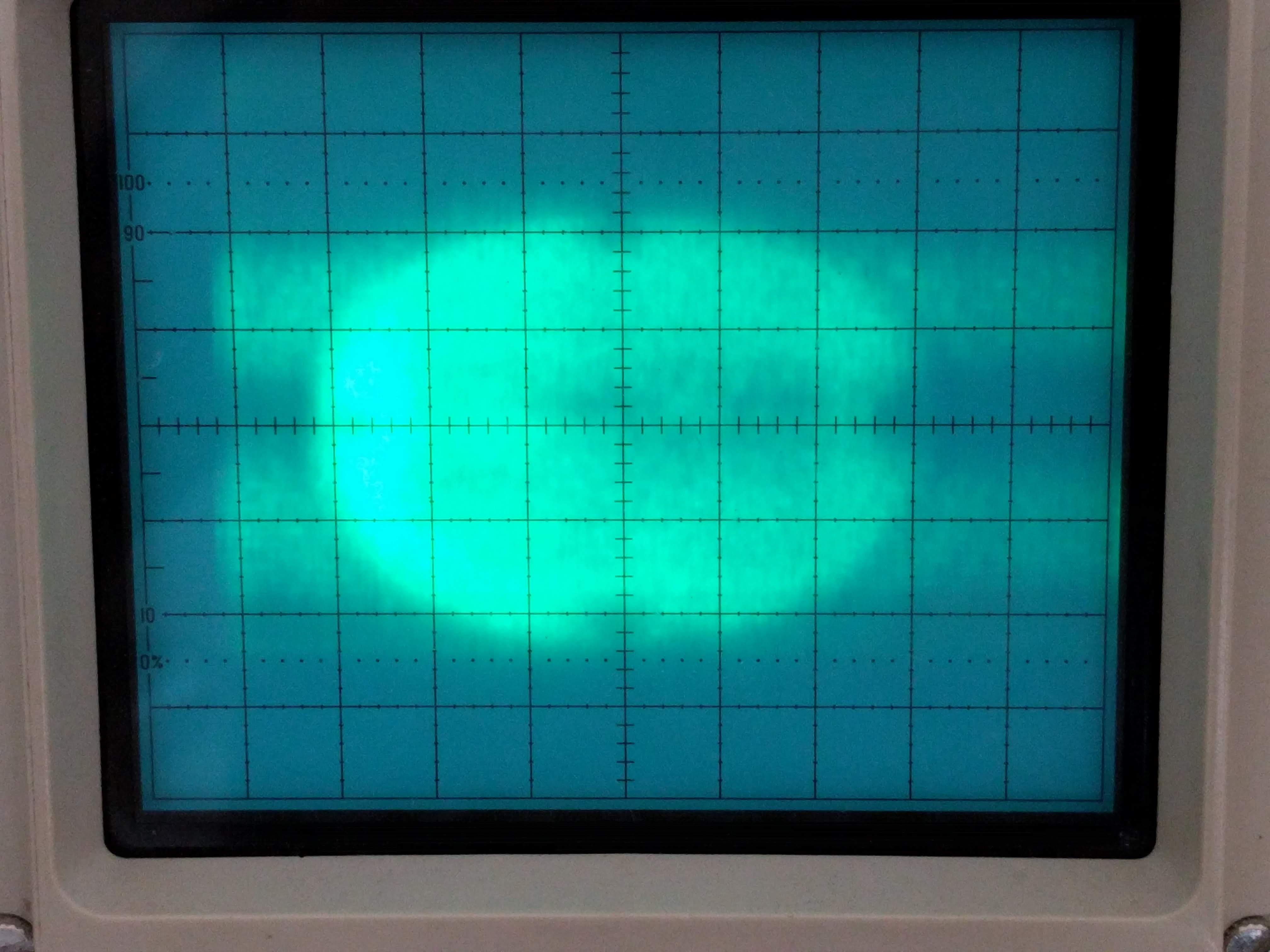
You can see the round shape of the target along with some marks in the edges. The darker bit in the middle are characters, but things are just too fuzzy to see them. Part of the reason was that the video amplifier I used had a gain-bandwidth product of only 4.5MHz. In a non-inverting amplifier circuit with a gain of 100, the bandwidth was only about 45KHz! This just was not enough. There was also some distortion in the deflection amplifiers.
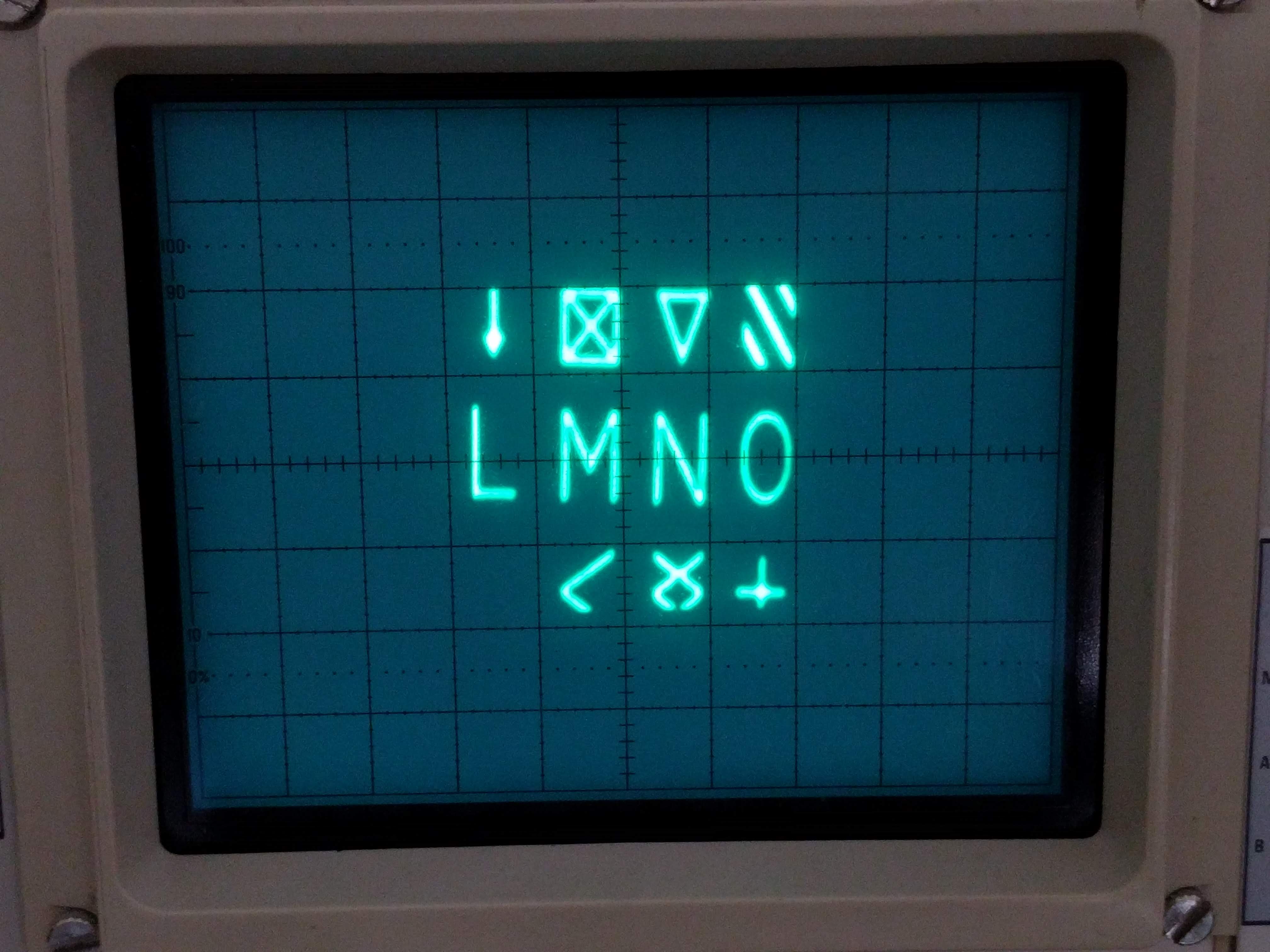
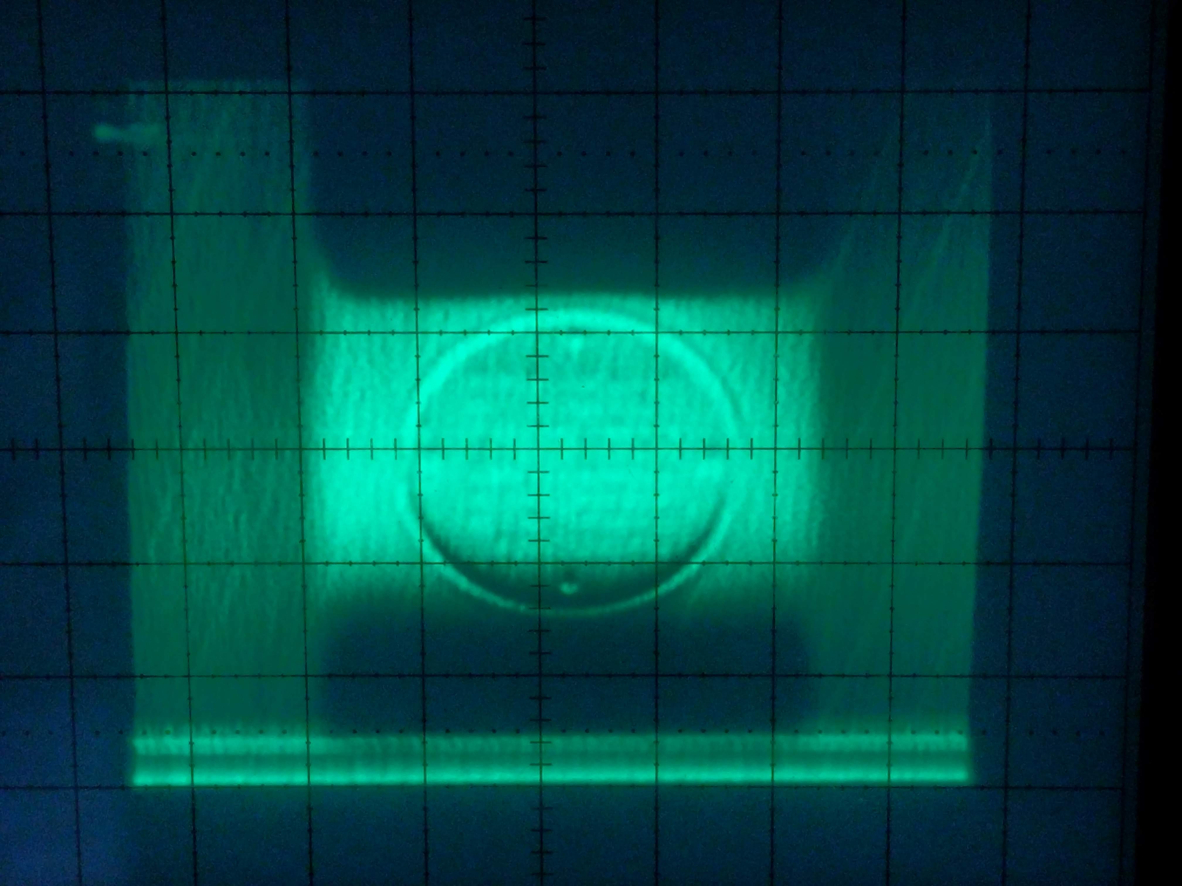
After adding another gain stage to the video amplifier and rearranging the circuit so that I could drive the deflection plates directly with some function generators, I saw this on my oscilloscope screen!
After a little research, I found out that the tube was used in some very early computer terminals including Raytheon’s DIDS-400 (c. 1967). To generate the display, the Monoscope was connected to a standard CRT. There were two sets of deflection circuits: one picked the character from the Monoscope while the other selected the location on the CRT. A pair of sine waves (really!) was fed to both sets of vertical and horizontal deflection plates, producing a raster scan which copied the character from one tube to another.
This worked quite well in the days before character generator ROMs. The tube acts essentially as an analog ROM.
Other companies combined both the Monoscope and the CRT into a single monster tube that had deflection plates, a mask with the character set, and a set of electromagnets that could rotate and position the character on the phosphor screen! Such a tube was called a Charactron(Convair) or Typotron(Hughes). A version of this tube was used in the computer terminals of the SAGE computer used in the US early warning radar system.
I decided to switch back to the higher-voltage deflection amplifiers to see if I could look at the entire character set at once. With the improved circuit, I got a better image:
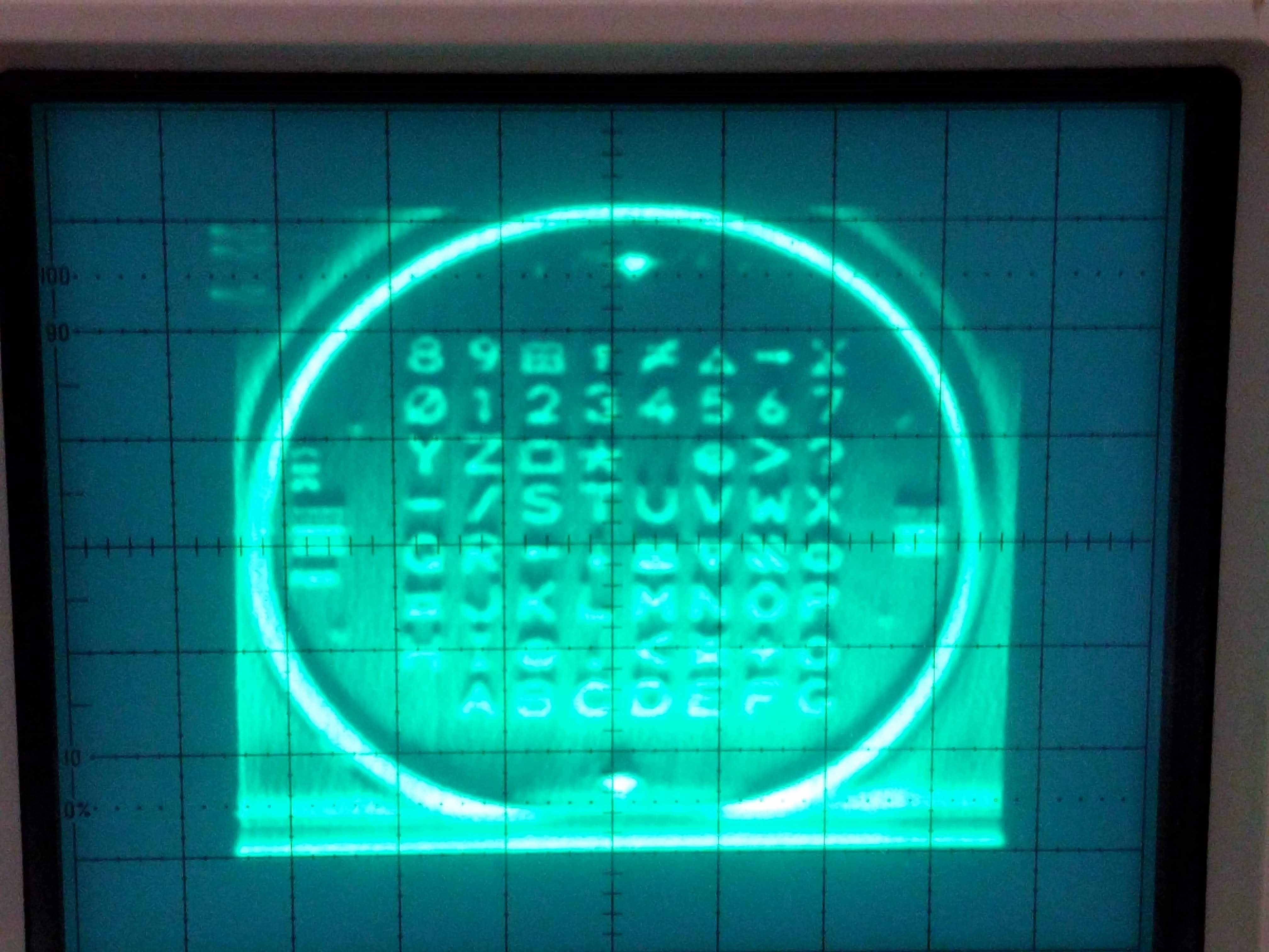
It took a bit of tweaking to get the image. You can see alignment marks and other features on the metal target disk.
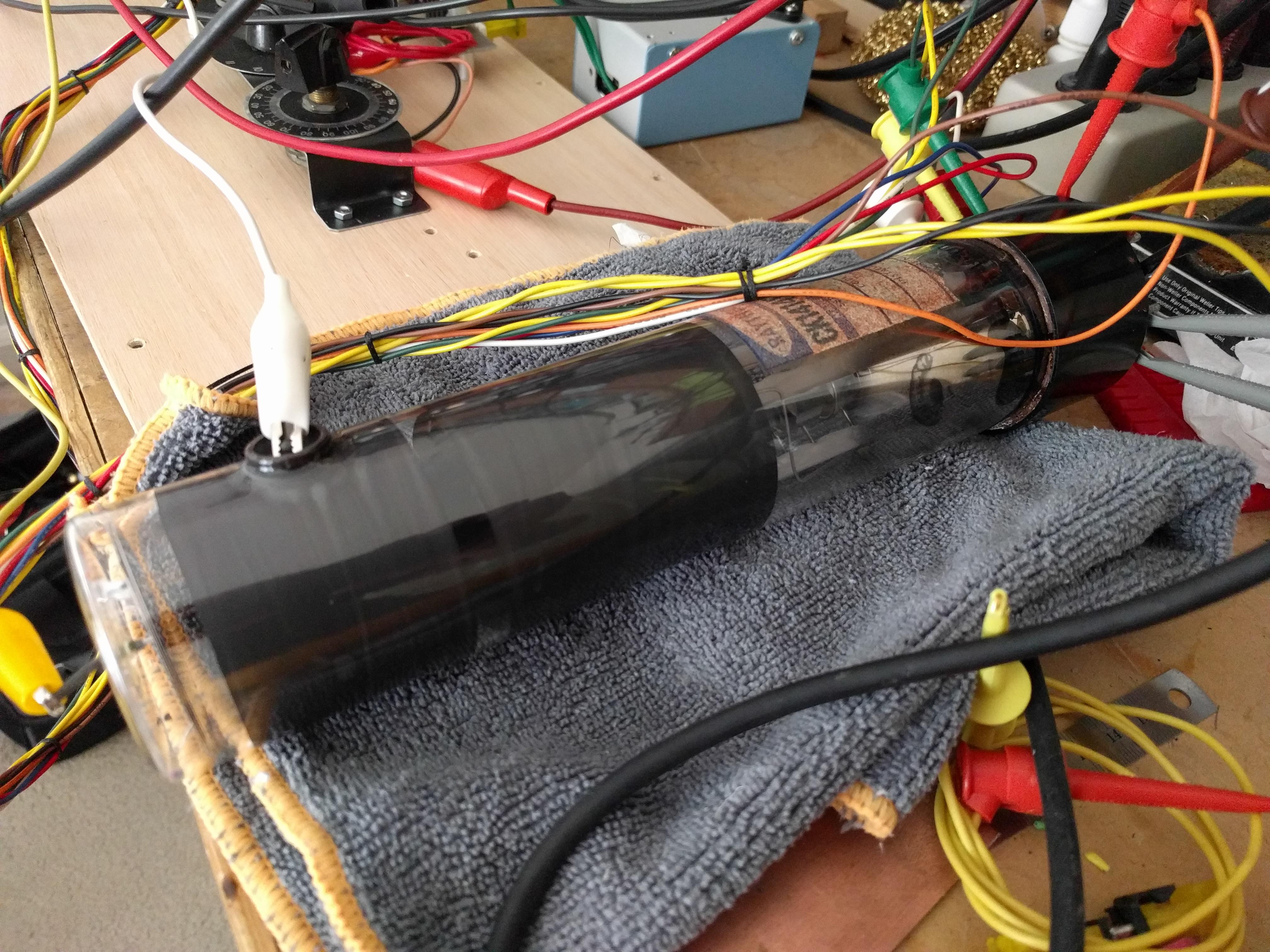
My setup looks like this:
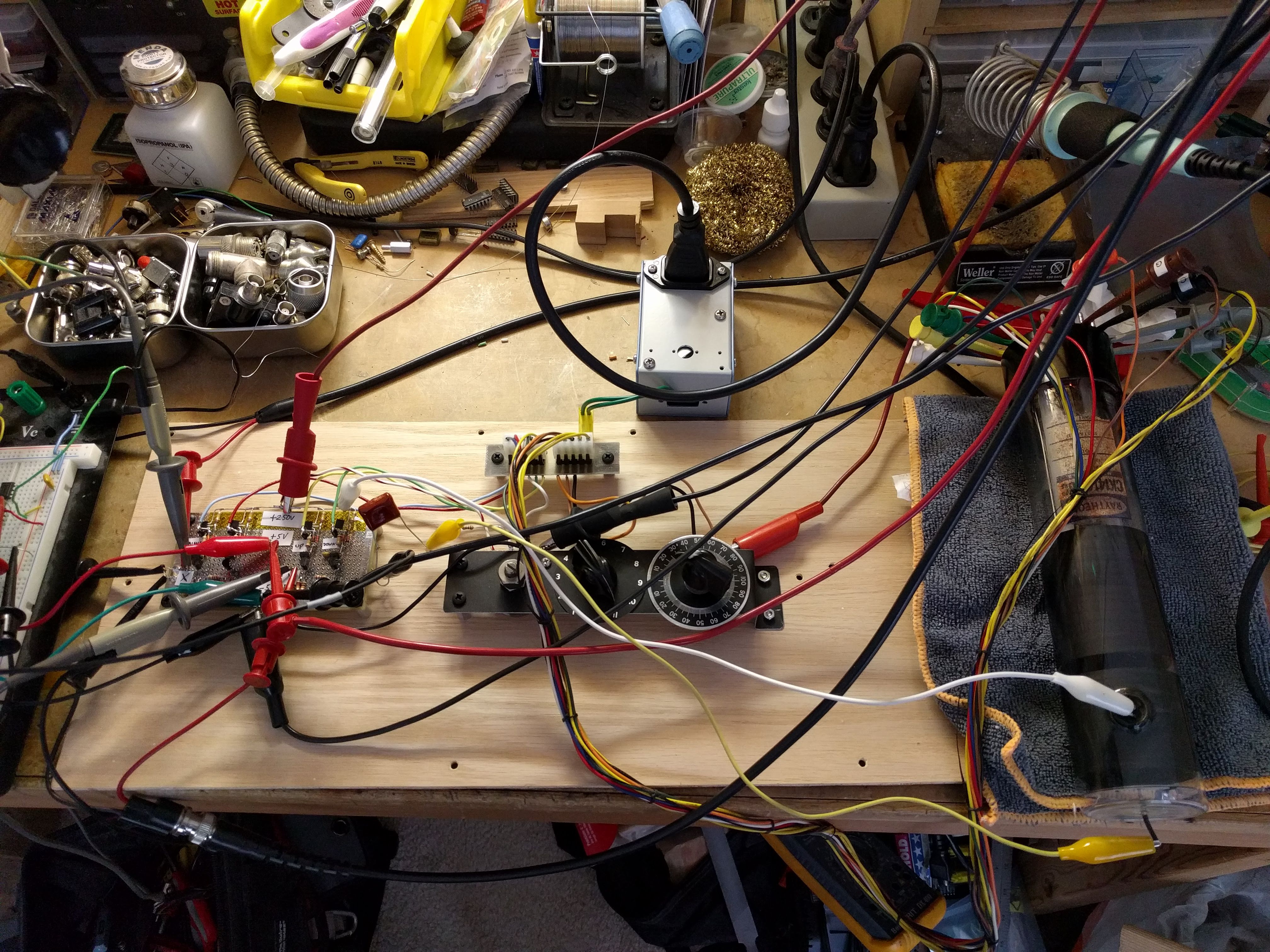
In the middle there are three potentiometers which control brightness (really beam current), focus, and astigmatism.
As I was shutting off the high voltage supply, the image shrank on my oscilloscope screen since the deflection factor decreased, and I saw something interesting:
The target is in the middle, but there are odd shadows on the top, bottom, and sides. These are actually the deflection plates! The left and right plates are nearer to the electron gun so they block the view of the top and bottom plates which are closer to the target. When I saw this, I realized that this tube is essentially a miniature scanning electron microscope–only there’s just a single, permanent sample since the tube is sealed.
If you have one of these tubes and you want to experiment, the circuit I used looks like this (click for larger version):
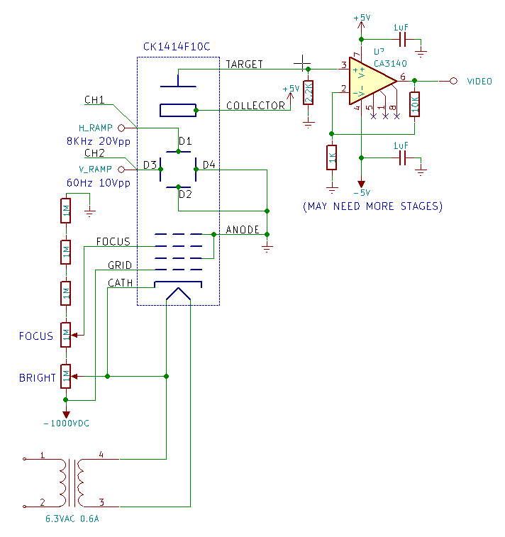
You will need a 1000V power supply such as one designed for operating a photomultiplier tube. Needless to say, high voltages can kill you and should be treated with respect; please take proper precautions when experimenting with this stuff. Ground the metal cases of the potentiometers or use insulated knobs so you don’t shock yourself.
Connect the oscilloscope channels 1 and 2 (in XY mode) to the deflection plate inputs. Connect the oscilloscope’s Z-axis input to the video output from the amplifiers. I’ve only shown one stage, but you’ll need more gain to get a good signal. The function generators should be generating rising ramp sawtooth waveforms, but even sine waves will work. If you can synchronize the two, then you’ll get a more stable picture.
The vacuum tube’s filament needs 6.3VAC, so I’ve provided that with a transformer. Please check the transformer’s datasheet to make sure it can withstand the 1000V between the primary and secondary. Often this is called out as the maximum isolation voltage.
Well, there you have it–when ROM chips didn’t exist, people stored data in miniaturized scanning electron microscopes!