August 24, 2010
Clocks, Projects
5 Comments
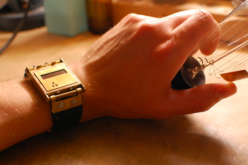
Is that…?
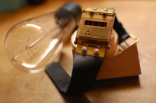
Yes, it’s an LED steampunk wristwatch! It uses the LED wristwatch board (see this previous post). The watch is constructed from a small piece of oak and pieces of brass sheet and tubing. I used hand tools, a Dremel tool and a cordless drill to shape and form each of the pieces.
There are four more LED wristwatch boards left. I wonder what style of watch I should make next…
Here’s one more picture.
July 31, 2010
Clocks, Projects
12 Comments
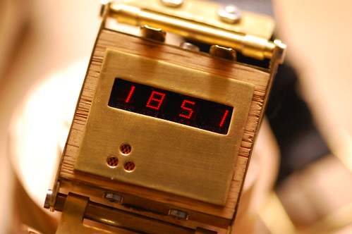
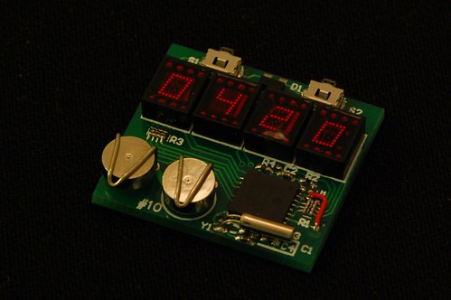
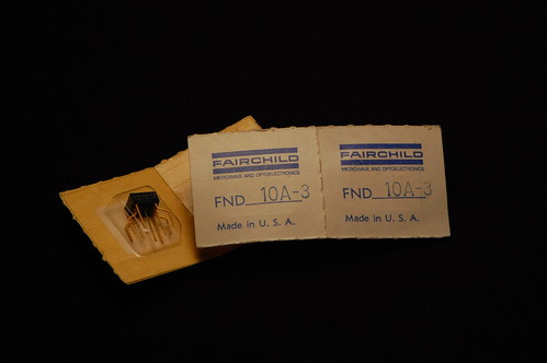
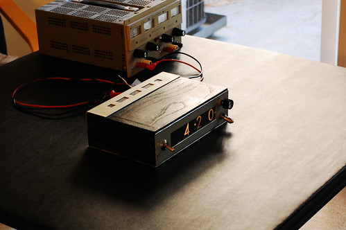
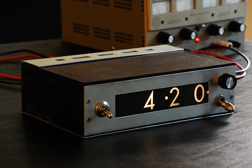
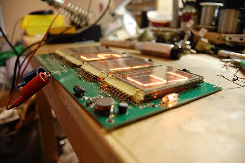
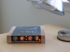
Sure, this doesn’t use a vacuum tube, but it’s still a neat way to reuse some old-fashioned 7-segment LED displays. OK, so I can’t wear it yet. It still needs a case and watch band. I am kicking around a few ideas, but feel free to post a comment if you have any suggestions.
The LED displays are quite tiny and would have been used for calculators or similar devices back in the day. They were made by Fairchild as you can see by the original packaging:
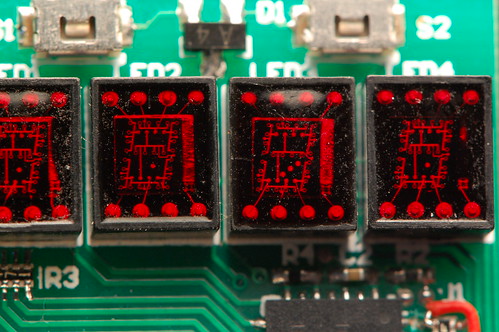
The unique thing is that each display has a single die inside with each of the segments etched into it. In the picture below, you get a pretty clear look at the bond wires and the top metal layer. If you click the image, I have annotated the Flickr page.
Back to the watch. It keeps the time with a fairly pedestrian PIC16F628A. It has an internal timer that operates with a separate oscillator (which is the watch crystal in the lower right corner) which can run even during sleep mode. This is critical to keeping the power consumption low. When a timer tick occurs, it generates a wakeup event, and the processor can increment the internal timekeeping registers. The processor can also wake up when one of the buttons is pressed. When that happens, it turns on and starts multiplexing the LEDs so that it can display the time. After a short delay it goes back into sleep mode. I haven’t yet calculated or tested the battery life.
The batteries are ZnAir number 10 (a common hearing aid battery). This is a zinc-air cell that uses oxygen as part of the electrochemical reaction, which is why there is a tiny hole in the top of each cell. Any battery holder has to allow air to make contact with the hole. In many states, these are the only batteries you’re allowed to throw away in the regular garbage. California is one of the exceptions, and the state considers zinc to be hazardous waste, so these batteries have to be collected separately in a category called “universal waste”. To me this seems foolish because I suspect that a lot more zinc is released into landfills as bits of scrap galvanized metal. Things like galvanized flashing, nails, and deck screws. Regardless of legislation, zinc is a lot less harmful than lithium, so remember to dispose of your burned-out LED throwies properly (and not in the regular garbage).
Here’s a puzzle for you: the PIC has 13 I/O pins. The LED displays use 8 (7 segments plus 1 decimal point) anodes and 4 cathodes. That leaves a total of 12 I/O pins, and I am not using the 13th I/O pin (RA4) because it is open drain and not useful in this circuit. So how are the two pushbuttons wired to the PIC? In fact, how can either button cause the PIC to wake up from sleep? Post a comment with your theory. I’ll give you one hint: there is a dual diode connected in some fashion to both switches.
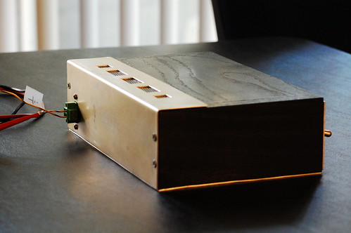
And here’s one last photo to give you an idea of how small this thing is:

April 28, 2010
Clocks, Projects
No Comments
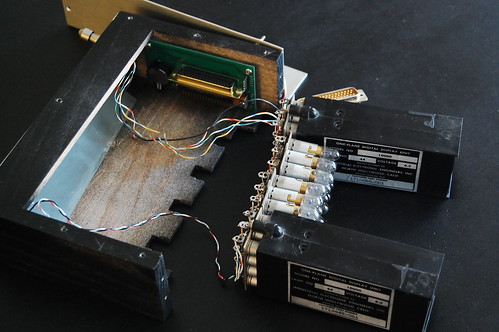
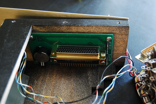
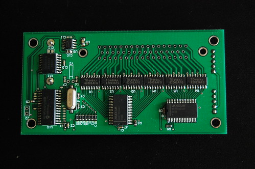
Let’s take a look inside the previous posted IEE clock:

Here you can see the laced wiring harness for the displays. This is not a multiplexed display–each of the 40 light bulbs has its own transistor driving it. All these wires come off the displays and into a very large DIN-style connector that plugs into the main circuit board. The ICs are all on the other side of the board.
This is a closeup of the main PCB. It’s quite small. You can see the PIC’s ICD header off on the right, along with a header that allows access to the I2C bus for troubleshooting.
And looking at the other side, we can see the driver ICs, the PIC, and the RTC device, along with some passives. You can also see the spare pads I put next to the PIC so that I can easily solder wires to the unused GPIOs if I ever need them.
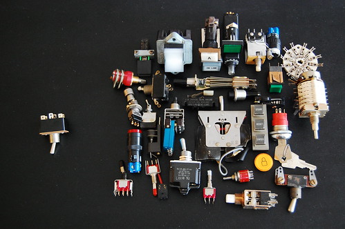
Some people commented about the switch on the front. I have a decent collection of switches of all colors, types, and vintages. It’s disconcerting for me to see what would be a really neat project marred by boring switches. Here’s a small sampling of my collection:
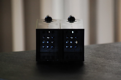
People really liked the photos of the disassembled IEE module from the other website. Here are a few gratuitous “artsy” shots:
April 25, 2010
Clocks, Projects
7 Comments
Update: more photos and information in the followup post.
Wow, things have been very busy lately–I moved to a new apartment, traveled to China, attended my brother’s wedding, and still had time to finish another clock!
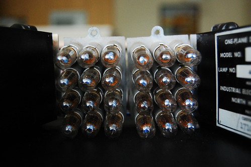
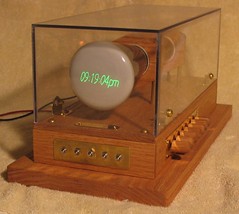
This one actually does have filaments. There are 12 light bulbs per digit; one for each numeral, and two for decimal points (left and right). These are neat little display modules that were made by a company called IEE (Industrial Electronic Engineers) way back before 7-segment LEDs were invented. Each light bulb sits behind a clear printed slide with the corresponding number printed on it in negative (the number is clear and the background is black), and in front of the slide is an array of tiny lenses. When a light bulb turns on, it projects an image of the number through the lens and onto the back of the lightly frosted plastic at the front of the display module. The Vintage Technology Association has a great exploded view so you can get a better idea of how this works.
The clock itself is fairly pedestrian although this design uses a quadrature encoder (the black knob on the upper right) to set the time. Instead of pushing on a button and waiting while the numbers slowly tick by, it’s much easier to just spin a knob.
Keeping time is the function of a DS3231 IC. The display is not multiplexed. A multiplexed display would involve a lot of diodes which would dissipate quite a bit of heat, and for this design, I use 6 ULN2003 driver ICs connected to 2 MAX7300 GPIO expanders. Technically I used devices that are pin compatible with the ULN2003 since nobody seemed to have any in stock. The microprocessor is a PIC18F2420 which communicates with the DS3231 and both MAX7300 devices using I2C.
Here is the back of the clock. You can clearly see the vents which allow the heat from the light bulbs to dissipate.
This clock will be at Maker Faire, so if you plan to attend, feel free to stop by my booth and take a look in person.
October 3, 2008
Clocks
7 Comments
Here are some photos of my latest clock. It uses large Panaplex-style neon-filled displays. I do not know the part numbers or the brand: these appear to be factory rejects, and each of the digits appears not to meet mechanical tolerances.
Under each digit is a reed switch that you can trigger using a magnet to change the number of that digit. The circuit board sits behind a regular picture frame where the glass has been painted black from behind. I masked off rectangular regions to allow the displays to show through, and I hand painted the “P” for the PM indication.
This is what the circuit board looks like:

The 180V power supply is on the lower right of the circuit board. The microcontroller timekeeping circuit is located underneath the leftmost digit. It is a PIC18F2420. I am using the onboard 32KHz oscillator with an external watch crystal, but I left room for a DS3231 timekeeping chip. It supports a battery backup, and you can see the place where it would go on the board right underneath the hour digits.
The left edge of the board has a row of header pins that I use to check the voltages, program the PIC in circuit, and probe the cathode voltages with a scope. The neon numerals have very interesting electrical characteristics, and eventually I will post an article about that.
Panaplex displays must be multiplexed to prevent damage. They are slightly more finicky than Nixie tubes, but the driving circuit is quite similar. I had to add a set of clamping diodes to limit the voltage swing on the cathodes (each segment is a single cathode).
This design was very fast and straightforward. I spent two evenings prototyping the circuit and getting the multiplexing working, another two evenings to enter the schematic and lay out the PC board, and two days to assemble, test, and finish the clock software.
June 18, 2008
Clocks
No Comments

Here is my first scope clock ready for assembly. The CRT is a 3GP1.
After assembly.
June 18, 2008
Clocks
No Comments
This is my first Nixie clock. It uses four multiplexed tubes and includes an alarm feature which wakes me up every morning.
There is no snooze function, and the alarm will continue to beep until I shut it off.
The microcontroller is a PIC, coded in assembly. It uses the PIC’s 32KHz oscillator to keep the time.
