
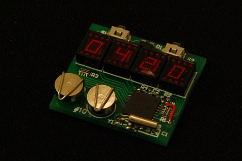
LED Wristwatch
July 31, 2010 4:02 pm Clocks, ProjectsSure, this doesn’t use a vacuum tube, but it’s still a neat way to reuse some old-fashioned 7-segment LED displays. OK, so I can’t wear it yet. It still needs a case and watch band. I am kicking around a few ideas, but feel free to post a comment if you have any suggestions.
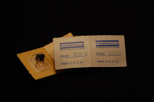
The LED displays are quite tiny and would have been used for calculators or similar devices back in the day. They were made by Fairchild as you can see by the original packaging:
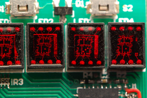
The unique thing is that each display has a single die inside with each of the segments etched into it. In the picture below, you get a pretty clear look at the bond wires and the top metal layer. If you click the image, I have annotated the Flickr page.
Back to the watch. It keeps the time with a fairly pedestrian PIC16F628A. It has an internal timer that operates with a separate oscillator (which is the watch crystal in the lower right corner) which can run even during sleep mode. This is critical to keeping the power consumption low. When a timer tick occurs, it generates a wakeup event, and the processor can increment the internal timekeeping registers. The processor can also wake up when one of the buttons is pressed. When that happens, it turns on and starts multiplexing the LEDs so that it can display the time. After a short delay it goes back into sleep mode. I haven’t yet calculated or tested the battery life.
The batteries are ZnAir number 10 (a common hearing aid battery). This is a zinc-air cell that uses oxygen as part of the electrochemical reaction, which is why there is a tiny hole in the top of each cell. Any battery holder has to allow air to make contact with the hole. In many states, these are the only batteries you’re allowed to throw away in the regular garbage. California is one of the exceptions, and the state considers zinc to be hazardous waste, so these batteries have to be collected separately in a category called “universal waste”. To me this seems foolish because I suspect that a lot more zinc is released into landfills as bits of scrap galvanized metal. Things like galvanized flashing, nails, and deck screws. Regardless of legislation, zinc is a lot less harmful than lithium, so remember to dispose of your burned-out LED throwies properly (and not in the regular garbage).
Here’s a puzzle for you: the PIC has 13 I/O pins. The LED displays use 8 (7 segments plus 1 decimal point) anodes and 4 cathodes. That leaves a total of 12 I/O pins, and I am not using the 13th I/O pin (RA4) because it is open drain and not useful in this circuit. So how are the two pushbuttons wired to the PIC? In fact, how can either button cause the PIC to wake up from sleep? Post a comment with your theory. I’ll give you one hint: there is a dual diode connected in some fashion to both switches.
And here’s one last photo to give you an idea of how small this thing is:

lan4t :
Date: August 25, 2010 @ 1:59 pm
I made a similar watch with Siemens DL440 module. I’ve been looking for smaller display modules to replace that with since. Where did you get those Fairchild modules from?
eric :
Date: August 25, 2010 @ 3:44 pm
The modules are from our local junk store, Weirdstuff Warehouse.
Alex989 :
Date: August 25, 2010 @ 8:32 pm
Hello will you release some kind of code, kit, or schematics? I will love to make one myself.
eric :
Date: August 26, 2010 @ 7:35 am
The LED displays were hard to find. I have only enough for the remaining 4 boards, so this is not going to be a kit. I do have a similar idea for a watch that could easily be made into a kit…
lan4t :
Date: August 25, 2010 @ 8:44 pm
Sometimes I wish I live in south bay. I’ll have to go to Wierdstuff more often.
Dr. Bob :
Date: August 26, 2010 @ 7:17 am
Very nice design. I have one of David’s nixie watches which too is a beautiful piece of engineering. If you start one, please add me to the list of people who would like to buy a kit of parts. Being a ID/ME type, not one of you electron jockeys, I can CNC my own case. I don’t even think about code – gives me a headache.
eric :
Date: August 26, 2010 @ 7:36 am
Thank you! One of my friends also has a CNC setup so I am thinking about giving him a board and seeing what he can come up with.
K Scharf :
Date: August 27, 2010 @ 11:56 am
Please post the schematic and source code. I still have about 1/2 a dozen of those display chips, got them at RatShack years ago.
Jonathan :
Date: August 31, 2010 @ 9:52 pm
Surely one of the following variations on Charlieplexing.
a. Some anode driver -> common cathode of dual diode, anode of dual diode -> switch -> some cathode driver in RB4..RB7
In display mode, drive only the cathode drivers of interest; all others in Z. To sleep, magic anode driver stays low and weak pullups for magic cathode drivers are activated. Poll once, if nothing set RBIE and sleep. RBIF wakes you up and the key down can be read directly from PORTB.
b. RB0 (a cathode driver) -> common anode of dual diode, cathode -> switch -> any two anode drivers.
Same general idea as a, but use RB0 as a key-down input (INTF/INTE) and hold the two anode drivers low during sleep. Upon wake, switch anode drivers between GND or Z to scan the keyboard.
Ronan :
Date: October 21, 2010 @ 6:04 pm
The trick for the buttons is quite easy, since you’re using it to differentiate input/output. What you’re probably doing is switching the PIC pins from output to input and vice-versa from time to time. That way you can use the cathodes to output high, then switch two anodes to input, and that will only conduct through the buttons if they are making contact, since the LEDs are polarized in reverse (acting as a non-conducting diode). Add a resistor to avoid a short and too much current when you’re driving the LEDs. With a pull-down for the button, you’re set.
Bill Sherman :
Date: May 29, 2011 @ 2:43 pm
Saw you at Maker Faire 2011. Fantastic stuff.Could you please post a schematic and source code. I would like to build one too.
Denis :
Date: July 18, 2012 @ 10:02 am
I don’t mean to be picky, but why would you have the buttons on top mounted to face away from the wearer? Also centering the LEDs would be esthetically more pleasing. Great work however, I love how you let the guts of the LEDs show and not cover it with a dark red plastic cover like it is usually done. Kudos, D