
Electrostatic CRT Driver Design
May 31, 2014 10:24 pm ProjectsUpdate 23-December-2014: Richard at LabGuy’s World has wiring diagrams for the RCA 913 and the 3JP7, and other neat stuff.
Update 23-June-2014: Please see the CRT Board BOM Updates page for important changes.
Update 3-June-2014: Added OSH Park links so you can order PCBs easily and quickly!
Well, it’s here! I’ve put together an open source release package for my CRT driver design. See all the glorious details at the GitHub project. It contains the fab data (Gerbers, NC drills, etc) as well as the CSV-formatted bills of materials for three boards. All the parts are available at Mouser Electronics (and the Mouser numbers are listed in the BOM). It’s the same set of boards that I used for my Asteroids and Flappy Bird arcade machines at Maker Faire.
The design can drive most 2″, 3″, and some 5″ electrostatically-deflected cathode ray tubes, such as the popular 3BP1 or the precision 3RP1A. It can be modified to drive some of the oddball 2″ and 3″ CRTs that have a shared heater and cathode connection.
The three boards are:
- 1KV power supply (Order from OSH Park)
- Electrostatic CRT deflection and video amplifier (Order from OSH Park)
- Video amplifier bias supply (Order from OSH Park)
The 1KV power supply takes +12VDC and uses a Royer oscillator with an off-the-shelf CCFL transformer to create filtered 800-1200VDC. The voltage is tuned by adjusting R1. Use a plastic-handled pot tweaker tool please! The supply can easily source several milliamps, which at 1KV could stop your heart. This is a serious power supply, so please be safe if you decide to build it. Keep one hand in your pocket while using it. Turn the supply off before poking at it, waiting at least a second or two after switching off the DC supply to allow the sense resistor divider to bleed off the output voltage. Don’t work alone.
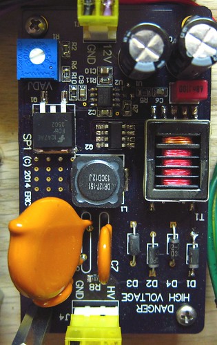
The design is inspired by CCFL circuits designed by Jim Williams–see the very long and wonderful AN65, especially Jim’s hand-drawn notes at the end. While Jim used a switching regulator to drive the Royer circuit, I used a simpler linear FET approach which works well but generates more heat. You will need to screw a metal heat sink to the plated through-hole located above Q1. Use a mica washer and a nylon screw if you want electrical isolation since this node is NOT ground.
If you want to put this in an enclosure, keep a clearance gap of 1cm or more between HV connections and low voltage nodes or a metal chassis. The power supply produces stray magnetic fields that will cause the electron beam in a CRT to deflect in ways you don’t want, so you should keep it far away from the CRT and use a CRT shield made out of high magnetic permeability material, like mu-metal or soft steel.
You can also add a voltage multiplier circuit, tapping in to diode D1, to generate post deflection acceleration (PDA) voltages. A 2-stage multiplier (as shown on the schematic) can generate 3KV which is fine for 3″ and 5″ tubes that require it.
At the heart of the design is the electrostatic CRT deflection and video amplifier circuit, which takes 0-3.3V analog signals for X and Y deflection as well as the video input, and outputs high voltage drive signals to the CRT.
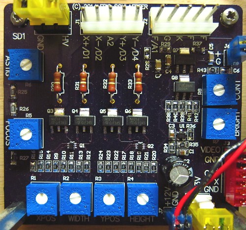
There are two deflection amplifiers, one for X and one for Y. The core of the differential amplifier is a matched dual NPN transistor with a bias circuit for setting the gain and offset (width/height and position potentiometers). A cascode stage made out of two high-voltage NPN transistors increases the bandwidth slightly and level shifts the signal up to about 1KV. There are two 220K resistors that form the load for the circuit. Don’t substitute these with plain carbon composition resistors–these parts have to be rated for high voltage use. Bandwidth of the amplifiers is about 10-15KHz, so you could drive ramp signals in to X and Y and generate an NTSC sweep if you wanted.
The video amplifier is a pretty simple class A design with a cascode stage to increase the speed. Bandwidth is about 6MHz, so the circuit can easily handle NTSC video. A simple-minded approach for driving a CRT electron gun is to ground the cathode and drive the grid negative, but the circuit design ends up being tricky. An easier way is to drive the grid to ground (or in my case, to an adjustable brightness voltage from a potentiometer) and connect the cathode to the amplifier output. The end result is the same, although there is a slight impact on the focus electrode. The video amplifier uses a +60V bias voltage which needs to be rather stiff since the drive current is fairly high (required to get 6MHz bandwidth).
A focus potentiometer produces a bias voltage for the focus grid in the CRT. It’s adjustable over a fairly wide range covering most 2″, 3″ and some 5″ CRTs, but if you’ve found some oddball CRT, you could always change some of the other resistor values.
The astigmatism potentiometer changes the final accelerator voltage relative to the average deflection plate voltages. Adjust this potentiometer if the spot on the screen looks oval instead of round.
There is a connector for a 6.3VAC filament supply. You don’t have to use an AC voltage, but be aware that pin 1 is tied to ground. You might want to measure the actual output voltage of the filament transformer (under load of course). I’ve found that most of them tend to run high (7V is not uncommon). Adding a series resistor can help prolong the life of the CRT.
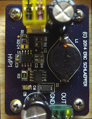
Finally, a video amplifier bias supply generates +60V for the video amplifier. As an “easter egg”, you could modify this circuit to operate as a Nixie tube power supply by changing the value of R1. You’ll also need to increase the voltage rating on C5.
If you’ve already looked at the GitHub project, you might have noticed that there are no design files. I use Altium Designer for my schematics and PCB layouts. It’s a fantastic tool, but Altium’s decided that hobbyists are not a target market so this is a very expensive product that not many hobbyists own, so I don’t think there’s much point to posting design files. Maybe if Altium releases a noncommercial free license, but I doubt that will happen. Altium recently raised their prices by $2K so the direction they are going in is pretty clear.
I’ll be posting updates with additional information, such as a CRT compatibility table, pin connection tables, and so forth.
Bob Coggeshall :
Date: June 6, 2014 @ 5:43 pm
This is awesome. I want to build them.
Sebastian :
Date: June 8, 2014 @ 3:11 pm
Hi, will this work on a 15inch TV to convert it to vector (i don’t need the HV i guess, the flyback is working nicely)?
Sebastian :
Date: June 8, 2014 @ 3:12 pm
Damn, after reading a bit more, and returning to a question i asked a while back on this site, i realise now that it won’t work. Too bad!
eric :
Date: June 8, 2014 @ 6:34 pm
it’s not going to work. but never fear! i’ve started working on a circuit to drive magnetic deflection coils. if you don’t want to wait, you could use the original Asteroids deflection board (in theory). the yoke will need to match the one from Asteroids, so you can’t just use the stock yoke from the 15″ TV. well, you might be able to rewind it.
Dan :
Date: June 8, 2014 @ 10:38 pm
Would it be possible to post the Altium schematics? I use it for school and I would be interested in seeing them.
Thanks!
eric :
Date: June 9, 2014 @ 7:36 pm
Working on it!
Dave :
Date: June 9, 2014 @ 8:08 am
I look forward to the connection tables.
Thanks for posting the board files.
Are they also gerbers if we don’t want to use OSHpark?
eric :
Date: June 9, 2014 @ 7:35 pm
Yes, Gerbers are in the Github repository.
Alessandro :
Date: June 10, 2014 @ 3:28 am
I suspect that on the ScopeDeflection pdf schematic the Vcc And Vbias connections around U1 are switched.
Did you prepare any Pspice file for us to play with?
Great job.
eric :
Date: June 12, 2014 @ 11:02 pm
thanks! no Pspice was involved.
Alessandro :
Date: June 10, 2014 @ 3:57 am
Never mind! My fingers where faster than my brain…
Etienne :
Date: June 16, 2014 @ 1:19 pm
Hi! I have two small vector crt tubes around, 3LO1i and 6LO1i (which uses the same pinout btw). I was wondering if those ones are compatible? Thanks!
eric :
Date: June 21, 2014 @ 3:14 pm
Etienne, I have tested it with the 6LO1i which works fine. The 3LO1i should work BUT you will need to adjust the value of R2. Try using 33K instead of 20.5K, and measure the output voltage of the supply before connecting it to the 3LO1i, which has a rating of 800V.
Richard :
Date: August 8, 2014 @ 8:54 am
Downloaded the Github files. Can’t open a single one. Adobe claims the PDFs are corrupted and the other files are not recognized. The so called .txt file seems to contain HTML or XML or other markup language. 🙁
eric :
Date: August 9, 2014 @ 9:35 pm
Sadly you can’t right click and download the Github files directly. You have to click the link for the file which will take you to a new page. On that page, click the “Raw” button and it will download the file. Sorry for the trouble.
Richard :
Date: August 8, 2014 @ 10:17 am
Managed to print out the three schematics. What a tease.
These kinds of sites absolutely never work for me. I must have the anti-knack. Can’t view the files. Can’t download them. Could not figure out how to place an order for all three (nine!) boards at once on OSH Park. Had to continuously sign in just about every click. Never found how to pay. Could not complete the order process…
Canceled my BitHub account in disgust. Can’t find a way to cancel OSH Park. I’d love to build and use your boards. I am absolutely blocked. Sorry Eric. Do you sell these directly?
Richard :
Date: August 8, 2014 @ 11:13 am
Alrighty then. Persistence, am I right?
Managed to order the boards. Now on to the BOMs. If I can just figure out how to view them….
BTW, don’t click on a board at OSH more than once. You will end up with multiple orders!
Rich
Richard :
Date: August 12, 2014 @ 3:56 pm
Thanks Eric. You rock!
I have now finally worked my way through the project site madness. Ordered the boards, 3 sets, and enough parts to build all three of these from Mouser. Will share my experiences putting it all together when the parts arrive. So many CRTs, so little time!
Bryan Mogensen :
Date: August 12, 2014 @ 6:26 pm
Cool do you still sell these kitted up? I have a ww2 9 inch magnetic deflection radar tube still in the case I would like to do this with. Just saw your post about the deflection coil as well. I would like to do that as well. really neat blog!!!!
eric :
Date: August 12, 2014 @ 7:18 pm
Bryan, I don’t sell these directly. The 9 inch CRT sounds neat, you should post photos! Unfortunately I don’t think you can get enough current out of my power supply board to drive it with sufficient brightness. Eventually I will post the designs for the magnetic deflection driver board, so you might be able to cobble something together with a different HV supply.
Richard :
Date: August 19, 2014 @ 9:07 am
Received all the parts for the HV and DEFL boards. Constructed all three HV boards last evening and tested them this morning. 100% success. All of them produce between 820V and 1,200V over the full range of the pot as advertised. Was able to assemble them using my old Weller soldering iron and head worn magnifying rig (nerd-o-visor). High voltage regulation appears excellent. Great job, Eric!
eric :
Date: August 24, 2014 @ 10:00 pm
Excellent! I tested load regulation using 2 megohm resistors in parallel. They got warm!
Dennis Bahr :
Date: November 3, 2014 @ 8:03 pm
Are the silk screen markings on J1 for D3 and D4 switched? I think the silk screen should read D1, D2, A2, D4, D3. Switching D4 and D3 allows my 3RP1A to work properly.
eric :
Date: November 4, 2014 @ 8:36 pm
It’s possible. Are you seeing a mirror image?
Dennis Bahr :
Date: November 7, 2014 @ 5:56 pm
Yes, that is what I’m seeing. Your design is nice since the pins on the PCB that go to the CRT follow in succession making wiring very straight forward. This is true for all pins. However, I need to connect D3 on the board to D4 on the CRT and D4 on the board to D3 on the CRT to get a correct picture.
Have you tried your board with the new Sparkfun AVR Oscilloscope clock?
I realize that your board may not have enough bandwidth, but I am having problems getting the Z-axis to work.
eric :
Date: November 23, 2014 @ 6:19 pm
Dennis, interesting about D3/D4. Do you have a link to the datasheet of the CRT you are using? I have not tried the circuit with the AVR oscilloscope clock. You might have to modify the source to slow down the output vector drawing. The Z-axis uses a positive-polarity video signal–3.3V turns the beam all the way on and 0V turns the beam off. I suspect the clock kit uses reverse-polarity video, in which case you would see very little. A simple common-emitter transistor inverter circuit should fix that for you.
Richard :
Date: December 13, 2014 @ 7:16 pm
Eric. How do you connect the CRTs with the heater and cathode sharing a common pin? 1DP1 or 913 for instance. I simply jumpered the non-ground side of the heater to the cathode connection. Not sure what I’m seeing. My scope died yesterday. Back to telepathic troubleshooting.
Richard :
Date: December 20, 2014 @ 6:56 pm
Success! Eric. To operate tubes with the cathode and heater sharing a pin, wire the 6.3 VAC around your board. Only connect the HK pin side to the K pin on the board. Now the AC power is floating free from system ground. Look for an update tonight at the bottom of my CRT project page: http://www.labguysworld.com/Project_ESCRTs_001.htm
Richard :
Date: December 21, 2014 @ 2:53 pm
The body count so far. One 3JP7. One 3UP1. Three 1DP1s, a 1EP1, a 1EP11 and three RCA 913s. Driving your boards with AVR scope clock or Tiny TV Mk2. Thanks Eric!
eric :
Date: December 23, 2014 @ 10:44 am
Loved the video!
Richard :
Date: December 24, 2014 @ 9:11 am
Oh. So you are reading this thread after all. I have to admit, the content of the last video was better than average. Still got those high standard Hooterville production values! Moved back to the scan board I designed years ago. I see that I included exactly zero emitter degeneration resistors in the diff amp. That could account for the excessive gain. I am going to add 150 ohms to all four emitter leads to drop the gain to around 100. Zero to three volts in to get +300 to zero volts out at the first MJE340 collector.
Do you think adding emitter bypass capacitors will improve the frequency roll off?
eric :
Date: December 28, 2014 @ 5:47 pm
That will let you increase the gain at higher frequencies. Try it and see!
Richard :
Date: December 27, 2014 @ 9:43 am
I got a decent reply from a fellow calling himself crobc1 on youtube. He has all kinds of actual helpful advice. Have told him to contact me directly. I think he should collaborate with us. See the comments section on this yout tube video: https://www.youtube.com/watch?v=bRuqud2j_d8&list=UUnurlZAW7G0ybfGFNhJkYBg
eric :
Date: December 28, 2014 @ 5:52 pm
He’s right about the bandwidth issues. It’s a tradeoff I made to simplify the design. There are a number of ways of solving it, such as making the average plate voltage “ground” and using a more conventional buffered +/-150V deflection plate amplifier, and then having a negative HV supply to run the cathode…
Andy_Chezz :
Date: January 8, 2015 @ 8:40 am
Hi Eric,
Great site.
Looking at ordering a set of the boards.
One thing holding me back though, the need for an external transformer supplying 6.3v ac.
I wanted to be able to produce a complete system that I can run from a 12V DC source.
I have tried a number of Google searches, but can’t find anywhere showing a 6.3v inverter circuit. For low voltage applications, people just run the heaters from a DC source.
Would that be possible with this equipment too?
Thanks.
eric :
Date: January 18, 2015 @ 2:49 pm
Andy–you can run a CRT filament on 5VDC if you want. Connect +5V to pin 2 of J4. (Pin 1 is ground and is tied to the main board ground).
peter :
Date: January 17, 2015 @ 2:53 pm
will you ever make prebuilds of these?
i dont have the hands to solder smd or even hold smd parts
eric :
Date: January 18, 2015 @ 2:45 pm
I hadn’t planned on it. Many of the parts are available as through-hole, so you might be able to construct it from the schematic.
Andy_Chezz :
Date: January 19, 2015 @ 6:21 am
Thanks Eric,
That’s great to know.
Andy.
Garry :
Date: July 3, 2015 @ 11:49 am
Eric,
Brilliant site. I ordered the boards and parts. Constructed the video amplifer just fine and seeing 60V just fine.
Now I started the 1KV power supply. It’s all built, but am not seeing any HV at all. My smt soldering skills aint great, but I’ve had a good look with some magnifying specs and all seems to be OK.
Now my electronic skills aren’t great, and I don’t expect an in depth hand holding debugging session, but any help or guidence where I can start tsting to see where the problem may lie would be greatly apprciated
Thanks
Garry
eric :
Date: July 3, 2015 @ 12:06 pm
Garry–Just work through the schematic section by section.
Garry :
Date: July 3, 2015 @ 1:29 pm
Eric I really appriciate the tips – I shall let you know what I find
Thanks
Garry
Garry :
Date: July 29, 2015 @ 8:11 am
Hi Eric,
Success! One working 1K power supply.
I followed what you said, there was no oscillations. I replaced Q2 and everything works!
I’ve assembled the deflection board, but its untested…. Shall report what happens if you are interested.
Thanks again Eric
G
Brandon :
Date: December 4, 2015 @ 2:33 pm
Hello Eric!
I have been a big fan of you and your blog for the past few months! I have always had a fascination with tube amplifiers (and generally ‘older tech’), and luckily stumbled upon your site while doing some random research. I am so glad I did!
I’ve have experience with a few audio projects over the years, but this will be my absolute first attempt with any sort of video – so I apologize in advance if I say something that makes me sound like an idiot.
I ordered the parts to put the boards together – along with a few random NOS CRT tubes – because I thought it would be a fun project to ‘practice’ with until I figured out the direction I wanted to go with it.
My questions were:
Would I be able to easily run your video board off of a computer’s VGA signal? VGA outputs separate (0.7v) red, green, and blue video signals as well as individual TTL-level (5v) horizontal and vertical sync signals. Would the unmodified 5v from the VGA sync signals be too much for this board?
I wanted to attempt using this as an external text-only display terminal to see how the different tubes compared with displaying text.
Thank you so much for providing us all with such great resources!
eric :
Date: December 10, 2015 @ 10:49 am
Brandon–it should work fine. If you ordered the vector (XY) deflection board then you will need to build a ramp generator so it can operate from the sync signals. See this post. You’ll probably have to play with the brightness and contrast controls to get the VGA video levels to show up on the screen.
Harry Lythall :
Date: June 19, 2017 @ 11:47 am
What a fantastic project. I had thought of starting from scratch, but this project seems to have everything I want.
Small question, I have a 6LO1I CRT, which has slightly different electrodes (at least in the Russian datasheet). Could this tube work in this project?
BR Harry
eric :
Date: August 16, 2017 @ 5:12 am
The 6LO1I looks like it would work. You’d have to experiment a bit with the focus voltage but it should light it up just fine.
Harry Lythall :
Date: August 22, 2017 @ 9:28 am
Thank you very much Eric. Your feedback is really appreciated.
I lit up the tube and it is giving a good display. The display changes with voltage from around 900V to 1300V and the intensity (G) voltage seems to change the astigmatism, rather then the intensity!
But I think I have just got to play with the values a little. If all else fails then I must read the specifications again 😉
Very best regards from Harry – SM0VPO
Alexandre from france :
Date: December 1, 2017 @ 1:05 pm
Hello, im very impressed by your designs and im thinking of building the supply and deflection boards to drive two CRTs, encased in one device (2bp1 or 2bp11). Thank you because this is very useful in my research.
Do i have to build two copies of each or can I tweak the design to save some parts ? I will make my own PCBs, for I cant surface mount.
I just want to display two discrete stereo signals and dont understand the use of the third board as i never looked into video signals yet. Is this board solely related to video or useful in my case?
Thank you again if you find the time to answer me. 🙂
eric :
Date: January 5, 2018 @ 1:10 am
You only need one deflection amplifier since you can share it between the two CRTs. You will need two video amplifiers so that you can provide a different video signal to each CRT. Since deflection is shared, you will need to blank one display while you paint the other one.
Mike :
Date: January 6, 2018 @ 5:59 am
Would it be possible to increase the bandwidth of the deflection amplifier to 1MHz or more?
I’ve got a 7BRP14 that I’d like to see what I can do with. I figure if I get around 1MHz that would be fine for 192KHz audio DAC as a driver, and maybe toy oscilloscope use.
I’ve got a video of it running with a single gun lit on YouTube.
eric :
Date: January 20, 2018 @ 2:51 am
Not easily, unfortunately. You could decrease the values of the load resistors in the diff pairs to increase the current, but you’d have to use much bigger transistors as well. You’d also need a bigger power supply. That’s pretty much a different board.
Nice tube!
Joost :
Date: August 26, 2018 @ 8:01 pm
Thanks so much for these circuits !
I am looking at the psu board and I am wondering if the ‘optional 3kv pda multiplier’ part has been tested ?
And am I right in assuming that the diodes are the same as D1-D4 and the capacitors the same as C7 ?
Chhuppa Rustom :
Date: July 18, 2020 @ 4:40 pm
Hi Eric, Are these boards available assembled ready to purchase or in kit form?
Madison Lindsey :
Date: February 5, 2021 @ 12:43 am
Can these boards still be purchased?
eric :
Date: February 14, 2021 @ 6:46 pm
The design is open but I am not selling them.
Brooks :
Date: May 19, 2021 @ 11:57 pm
Hi Eric! Thank you for sharing this project. I’ve been working on a project where I want to overhaul the internals of this old portable radio-TV for music visualizations, controlled by a modern microcontroller. I’ve been doing research on how to solve the CRT part of the project, and this looks like a good starting point.
But I’ve been unable to find any information on my specific CRT tube model and its socket-type. I’ve searched for any and all the various part numbers on it. All I know for sure is it’s a 5″ B/W tube.
Is there any chance you could take a look at this imgur album and share any insights you might have on its compatibility with your project? I also have the service manual for the entire unit, with schematics, if there’s something specific I should look for you can direct me to, but there is not much detail on the tube itself than what I’ve already found.
Thank you very much for your time.
eric :
Date: July 17, 2021 @ 10:48 pm
Why not use the TV circuit to drive the tube? This type is magnetically deflected, and you can modify the deflection yoke so that you can drive it with a regular stereo audio amplifier. I have more details on winding deflection yokes at this blog post.
Jonathan :
Date: September 8, 2021 @ 9:08 am
Eric,
The transformer on the psu board seems to be obsolete at mouser and cannot find any alternatives, do you have any alternatives I can look for?
Thanks in advance!
eric :
Date: January 18, 2022 @ 11:51 pm
Not at this point. The design is getting old and I need to go redesign it again. Maybe after the parts shortage lets up.
tube radio :
Date: March 31, 2022 @ 7:02 pm
I like this project.
Would the video amp work with the blanking pulses from the dutchtronix oscilloscope clock board?
http://www.dutchtronix.com/ScopeClock.htm
I’m looking for a way to add blanking to my two clocks using that board.
I’d like to build the whole set of boards you have, but that clock requires at least over 1MHz bandwidth from the deflection amps due to how it draws the vectors with what isn’t intended to be seen drawn much faster so that blanking is technically optional.
Also 1KV for the CRT wouldn’t be high enough to display bright enough for the CRTs I have which are a 5DEP1, 3RP1A, 5ADP1 & 5BP4. How would I alter the circuit to be able to use 2KV with the deflection amps and astig control still operating on 1KV?
Chris :
Date: March 8, 2024 @ 1:12 am
Hi Eric,
I’m trying to obtain the CFL transformers for this project but they are now obsolete.
(CTX210605-R)
Do you have any suggestions for a supplier or alternative?
Regards,
Chris