
Oscilloscope Video Monitor
March 29, 2011 Cleverness, Projects 12 CommentsWatch this YouTube video, and then read the rest of the post.
So how did I do it? It is actually a very simple circuit.
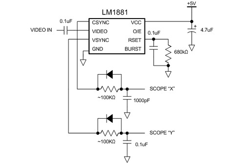
The LM1881 separates the sync signals from the NTSC composite video coming from the camera. It outputs a vertical sync signal (active low) that asserts during the vertical retrace period and a composite sync signal (also active low) that asserts during the horizontal retrace period and also during the vertical retrace period (but with a set of serration and equalization pulses).
To connect these to my oscilloscope, I have to use the XY mode on the scope and convert the sync signals into deflection signals. This is done using analog ramp generators. The simplest way is to use an RC circuit to generate a rather nonlinear ramp. When the sync signal goes high, it charges the capacitor through the resistor. When the sync signal goes low, the diode allows the capacitor to discharge immediately. This generates the sawtooth waveform. Adjust the R value so you get the most complete ramp (goes most of the way up to 5V).
The video signal is fed directly into the Z-axis signal at the back of the scope. Because the Z-axis signal has the opposite polarity from regular video (it is a blanking signal, where a positive voltage will turn the beam off), I had to build a really basic video buffer to invert the signal. This is a nice exercise in transistor biasing using four external resistors. Don’t ask me for the schematic–you should try to build it yourself. Even if you don’t get it working properly right away, you’ll discover all sorts of interesting analog video effects!