
555 Contest Entry
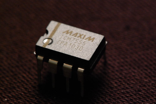
February 23, 2011 Projects 30 CommentsYes, it’s not really vacuum tube related, but I built an entry for the 555 timer contest. It uses an ICM7555, which is Maxim’s second source of Intersil’s CMOS version of Signetic’s original NE555 timer. Turns out the fact that it is CMOS is important for this particular circuit…
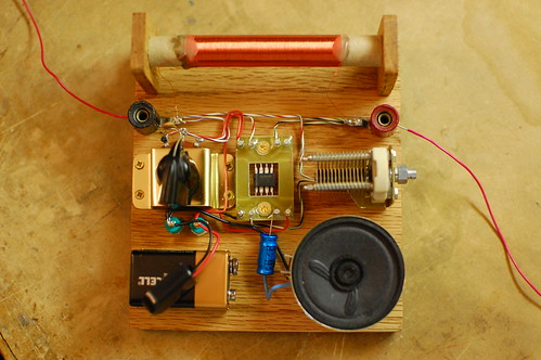
My entry is an AM radio. The only active device (silicon, germanium, or otherwise) is the ICM7555. The tuning is accomplished with an inductor and a capacitor, and the ICM7555 acts as an AM demodulator and class-D power amplifier to drive the speaker.
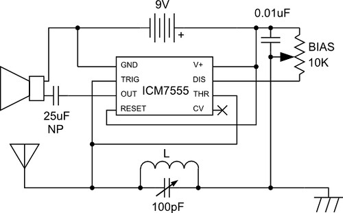
You may be wondering how all this is accomplished with a 555. The schematic is below.
Here’s how the circuit works: The AM radio signal is tuned by inductor L, which is 300 turns of wire on a 1/2 inch diameter cardboard tube made out of an old toilet paper roll, along with the 100pF variable capacitor. One end of the parallel configuration of L and C connects to an antenna (surprisingly long!) and the other end connects to a ground wire which is tied to the AC outlet ground (old books tell you to ground it to a water pipe). So far this is exactly like an AM crystal radio.
The 555 timer is configured as a pulse width modulator in a non-traditional configuration. If I used the standard approach and connected the input to the CV pin, the low impedance of the pin would prevent the circuit from receiving any radio signals. I had to invert the circuit and tie both high impedance analog pins, Threshold and Trigger to the radio signal input. This is the reason why the CMOS version of the 555 timer performs much better than the standard bipolar, which has higher input bias current.
The pulse width modulator ramp is created by the 0.01uF capacitor and the 10K bias potentiometer which are connected to the Discharge pin. The potentiometer wiper goes to the LC arrangement. With no radio signal coming in, the voltage on Threshold/Trigger ramps up until it hits the threshold, and then Discharge causes the voltage to ramp down again.
When a radio signal comes in, it gets superimposed on the ramp signal, causing the threshold and trigger comparators to trip early or late in a cycle. This variation causes the output duty cycle to vary, which we can hear as sound in the speaker.
Demodulating the signal properly requires adjustment of the bias knob, so that part of the radio signal is “clipped” and ignored by either the threshold or trigger comparators. This ensures that the negative “halves” of the radio wave don’t cancel out the positive “halves”.
Want to hear what it sounds like? Check out the video below:
And of course, I can’t end the post without a gratuitous shot of the ICM7555 in circuit.
