Social Media Update
December 19, 2022 Uncategorized No CommentsFind my latest posts at Bluesky (https://bsky.app/profile/tubetime.bsky.social). I’ve also been active since 2022 on Mastodon as @tubetime@mastodon.social.

Find my latest posts at Bluesky (https://bsky.app/profile/tubetime.bsky.social). I’ve also been active since 2022 on Mastodon as @tubetime@mastodon.social.
Since it’s hard to search Twitter, I’ve put together a compilation of some of my best Twitter threads.
Welcome thread #1
Welcome thread #2
Micropodcast Episode 1
Dipped tantalum capacitor (my first cross section)
LMR-195 cable
Fiber optic cable
Undersea cable
Ethernet plug and jack
VGA cable
Type N connector
Type N connector (annotated)
Apple Magsafe connector
DVI single-link cable
Tantalum capacitor from Fluke 8400
BNC plug and jack
Flat phone cable
RIFA paper capacitor
SFP DAC cable
BGA package
USB-C connector
AC power cable
MAX233 chip
Another USB-C cable
Micro SD card
Magsafe 2 connector
DIP socket
Glass thermistor
DIP socket (machine pin)
Carbon composition resistor
Blown LED
Micro-D connector
Modern BGA SoC
MacBook power cable
HDBNC connector
Axial aluminum electrolytic capacitor
12AX7 vacuum tube
Slowly rotating and dramatically lit cutaway view of a 12AX7
12AX7 vacuum tube (behind the scenes)
2N2222 in a TO-18 metal can
Bi-color red/green LED
2N3904 transistor (TO-92)
1N914 diode
DE-9 plug and socket
Headphone plug and jack
Electrolytic capacitor
15-turn potentiometer
Audio transformer
BGA chip
Quartz crystal (HC-49)
Electret microphone element
LR44 alkaline button cell
Vibrator motor
DIP switch
Film capacitor
Inductor
Tact switch
Magnetic speaker
Slide switch
Ceramic chip capacitor
Reed relay
Polymer electrolytic capacitor
SMA connector
Ethernet transformer
LED
Prototype XL741 Kit
Fencing scoring machine
Zenith Minisport
HP125 keyboard reverse engineering
1982 DisplayPhone video call
Northern Telecom NT6K00AN DisplayPhone from 1982
MOS 6581 sound chip — aka the Commodore SID chip — slowly rotating and dramatically lit
slowly-rotating, dramatically lit Yamaha YM3812 OPL2 synthesizer chip
The KIM-1 lives!
Just wrote my first blink-an-LED program for this microcontroller, which is quite special…
Today i dug up my first mobile computing device. i bought this over 20 years ago. i wonder if it still works…
Two identical-looking Commodore mouses aren’t compatible. Why?
Epson HX-20 repair
Epson HX-20 thread
New Apple laptop this weekend. New to me anyway.
Fischertechnik robotics kit.
Prototype Connor IDE hard drive.
Atari 800 connected to modern PC
Rockwell AIM-65 computer with the MOnSter 6502!
GEOS on the C64.
Rebuilding a C64 power supply.
UNIX computer that uses audio cassettes for storage.
The Xerox Notetaker from 1978, the first computer to ever be used by a passenger on a commercial flight.
Say hello to the Intel SDK-86, the first computer to use the 8086 microprocessor!
AIM65 keyboard repair
Unusual keyboard keyswitch
There’s nothing quite like the ear piercing screech of a dot matrix printer generating a line full of ‘#’ symbols.
AIM-65 says hi
Cursed 3mm audio plug. Yes, it’s an Apple product.
35 years ago today, the Amiga 1000 was born!
Amiga 1000 secret RAM
Resurrection of an Amiga 2000 motherboard.
Commodore CDTV
Amiga 1200 RAM expansion
Swapping out 200-pin Amiga CPU connectors
New Amiga 3000
SOIC pin repair.
Amiga 4000 with Toaster Flyer
GVP RAM for Amiga 2000
Experiments with Toaster Flyer 4000
Amiga ROM adapters for 27C4096 EPROMs to 27C400-style ROM pinouts
Amiga 1000 ROM easter egg
Amiga 500 with a PC hidden inside
Extreme Amiga 4000 repair
Amiga Brataccas with unusual copy protected disk
Amiga ticking floppy drives
IBM PS/2 Model 95 computer experiments
IBM 7496 executive workstation video review
PCI versus microchannel slot
PS/2 floppy adapter thread
Installing OS/2 2.1 on the PS/2 model 50Z
OS/2 2.1 thread
Replacement plastic fasteners for IBM PS/2 systems
Field stripping my PS/2 Model 50Z
PS/2 model 50Z drive sled (3D print)
MCA bus experiments
Expanded memory card experiments
ISA bus IO_READY signal
Exploring the light pen
Experiments with 90MB Iomega Bernoulli cartridges
Rev A IBM 5150
Presenting a Targa video card from the mid 1980s
Experiments with the Targa 16 video card
Three monitors on an ISA bus computer
Graphics demos for the IBM EGA
Number Nine Revolution 512×8 graphics card from 1984. It was one of the first hardware accelerated cards available for the IBM PC!
Windows 95 UI book is *glorious*
Iomega’s Bernoulli box of 1982 was *not* the first floppy disk to use the Bernoulli principle.
Imaging Bernoulli cartridges.
The official IBM game control adapter has several unusual features.
Extreme 486 motherboard hacking.
Early MDA graphics cards could actually do color!
The original IBM PC had a cassette port
Found something strange on an 8″ floppy disk.
Metheus Ultra Graphics Accelerator 1104 has only two video modes: 1024×768 and emulated CGA at 960×600!
Extreme Sound Blaster 16 repair.
Unusual Okidata gm3315b 5 1/4″ floppy drive. It’s thin!
The Intersil IM6100 is a PDP-8 on a CMOS chip! What should I do with it?
Scopetrex build thread
Announcing the SCOPETREX — the vector gaming console for your oscilloscope or XY monitor!
Plaid Bib build thread
Plaid Bib announcement
Plaid Bib CPLD announcement
Snark Barker MCA engineering thread
Roland MPU-IMC card
Open-source clone of the IBM extender and receiver cards for the IBM 5161 expansion chassis!
IBM extender board thread
Announcing the Snark Barker MCA!
Wanted: your *broken* old Sound Blaster 1.0, 1.5, or 2.0 cards. That DSP needs to get dumped!
Snark Barker build thread
Clones of my Snark Barker SB 1.0 clone are apparently now available in Hong Kong.
A CDP1802 breadboard computer that starts simple and gets complicated
I made a controller for my Vectrex clone today!
Own an IBM PS/2 model 50, 50Z, or 70 with a broken proprietary floppy drive? Here’s a way you can make your own replacement out of some 3D printed parts and a standard PC floppy drive!
MOnSter 6502
MOnSter 6502 running validation program.
Fixing my Fluke 8400A digital voltmeter.
A look at my private stash of Nixie tubes!
One of the first digital voltmeters, the Fairchild 7100.
The bad tantalum cap in my frequency counter that started the cross section project
Power your Nixie tube with a coin cell!
One of my Nixie clocks that I built almost 13 years ago.
One of the world’s first electronic calculators, the Friden EC-130.
Testing vacuum tubes
Some unusual vacuum tubes
Using a VFD display as a triode
In 1959, GE tried to convince the world that vacuum tubes were better than transistors.
Oh look, it’s a vacuum tube module from a 1950’s IBM computer!
It’s tube time! well, time to sort and test some vacuum tubes.
A 120 year-old light bulb!
The Sony Watchman has a very weird “flat” CRT
Fired up my Sony Watchman today, and I actually found an analog TV broadcast
Check out this neat CRT display!
Playing with CRTs today. I can almost hear the sound effect this visualization pairs up with.
3D vector clock with three CRTs
A CRT with P7 long persistence blue/yellow phosphor
My friend’s TV pattern generator uses a tube called a Monoscope
First image from the Raytheon CK1414F10C Symbolray character generating tube.
Got a package dated June 28th, 1944.
Tidying up this tabletop Battlezone arcade machine I built
This cool 7-segment display uses neon instead of LEDs
Check out the archives of the Journal of the Society for Information Display.
Imagine it is 1935, and you’re trying to troubleshoot a circuit. How would you look at a voltage waveform?
Come to California Extreme! Come play my vector tabletop arcade games!
Don’t have a proper vacuum tube socket for a 7 or 8 pin miniature tube? Tear apart a solder cup DE-9 socket!
This is weird, someone is still broadcasting in UHF!
Do you remember that high-pitched whining sound that old school tube TVs used to make?
Let’s take apart this old TV camera!
This is the 26 x 72 foot (8 x 22m) crater resulting from the gas pipeline explosion in San Bruno in 2010.
This Tesla SUV ran into a traffic barrier at 70mph while on Autopilot. How could this happen?
This electrical transmission tower has a little problem. Can you spot it?
A tiny company nobody had heard of, Cadtrak, sued Commodore for patent infringement and won
All right, this is a new one. A EULA on…fruit?!
This happened to a Boeing 787 while it was parked at Boston Logan back in 2013
Celebrate Beethoven’s birthday by listening to this *remarkable* recording from 1944
Why does the schematic symbol of a bipolar transistor look the way it does?
Performing computations with DRAM
Some neat IC die photos
A very clever radio transmitter circuit
Investigating a tunnel diode
I once made a transistor out of a germanium diode and a guitar string
When the first IC chips came out, General Electric fired back, introducing the Compactron in 1961.
How did people simulate heat transfer, fluid flow, and electric fields before we had fast computers?
Repairing a vintage analog oscilloscope
Weird diodes
Wanna see an old telephone stepping relay in action?
Troubleshooting the pulse dialer on my Automatic Electric type 80.
Fixing my other logic analyzer, the HP1661A.
An incredibly rare transparent SOIC chip package.
Let’s talk about multipliers!
Here’s the Intel 1702, the first erasable, programmable read-only memory (EPROM) from 1971.
You’ve never seen this D-sub connector before!
D-sub connectors were invented in 1952 at Cannon by Sam Arson!
This neon lamp should never light up!
Parts inside parts
Here is part of the payload electronics from the Explorer 8 satellite (1960)!
I went to the first Bay Area Maker Faire back in 2006. Here are some of the photos
Today i finished building an AM radio for the @hackadayio circuit sculpture contest.
I decapped this LH0070 precision 10V reference, and found something unbelievable inside.
Some IC chips come in clear plastic. I picked up a tube today.
Let’s look at old school LED displays under a microscope.
Troubleshooting the STM32F407 USB bootloader
Let’s take apart this old chart recorder!
This is the uA702, the first commercial analog chip (an op-amp).
Here’s a fun little mystery! See this 2N2222A transistor…
Here’s an interesting part, the LM399H voltage reference.
This desk fan is 85 years old and still running strong. How would YOU design an electronics gadget to last 100 years?
Hey look it’s an ultra-rare transparent IC chip!
TIL about stakeless earth ground measurement.
It’s not always a software problem. It’s not always a hardware design problem.
Measuring propagation delays through buffers from different logic families.
Fixing a 1960s Japanese transistor radio.
Here’s a fun little cascaded Peltier cooler. Let’s see how cold it gets!
Time to visit the giant 2N696 in person!
You may have heard of an IC named after someone, but have you ever heard of a chip *pin* named after a dog?
Let’s read this @digikey catalog from 1987!
Illegal RC car!
Check out this cool prototype LED!
Discrete breadboard version of 555 timer
Around 1994 I built this voice recorder box with my grandfather. I wonder if it still works…
This is an EMP-20 device programmer from the early ’90s. it supports a huge variety of devices. The thing in the side that looks like a SIMM socket? It’s not…
Surprising facts about electrolytic capacitors
Altered chips
The first commercial product I ever designed
Here’s a nuclear battery in a DIP package.
PSA – Don’t store your chips in that black ESD foam!
Built a phono preamp
Why are chips often so expensive?
Reverse engineering the IR3E02 chip “DMG-REG” from several Game Boy variants.
Here’s the Snappy Video Snapshot. It is a video digitizer.
This computer has a really neat VGA BIOS screen with a shimmering rainbow
This is an LM168 voltage reference.
Time to extract some bits from this ROM image.
This is the chip layout of the famed Intel 80C51 showing all of the basic functional blocks.
Today I confirmed that I have a bit-accurate dump of the Sound Blaster CT-1351V202 DSP 2.02 firmware!
Sep 14, 2019
Aug 10, 2019
Jul 13, 2019
Jun 8, 2019
May 11, 2019
Apr 13, 2019
Mar 9, 2019
Sep 8, 2018
July 14, 2018
Apr 14, 2018
An off-brand capacitor failed on me, so I made a TV commercial
Here’s the new proposed USB-C connector.
I didn’t have a terminator for a 1/4″ audio jack, so I had to improvise…
Salesman: *slaps roof of 7805* this bad boy can fit so much magic smoke in it
What kind of sadist makes a breadboard that is 3 rows too short to fit a 40-pin DIP?
Since everyone’s reviewing emojis, let’s look at the light bulb emoji.
Aren’t D-sub connectors neat? Here is a DA-15 (bottom) along with a… hmm… hipster D-sub.
Saw the Jameco truck at Excess Solutions today.
Let’s order strange things from NIST! First up is this jar of reference peanut butter.
7 segment LED? Nixie tube?
Prototype 4″ floppy disk drive
Prototype BART ticket card with magnetic stripe
World’s first hard disk head
First prototype of the Hercules graphics card
I see your bit and byte, and I raise you a prototype head for the world’s first hard drive, the RAMAC.
This is a module from the IBM 4 Pi series aerospace computer. Not bad for 1972!
Here’s the wire-wrapped prototype of the original IBM PC (5150) motherboard!
The WeirdStuff sign has turned off for the last time. 🙁
WeirdStuff megathread: What’s your best memory of the place?
Vintage laptops at WeirdStuff!
Super clean IBM PC convertible at WeirdStuff
Yep, HSC is closing.
HSC electronics is up for sale.
HSC electronics sure was expensive back in the day.
The photo is HSC Electronics (their old building). The coffee machine was just to the left out of the frame.
HSC electronics has been sold to Excess Solutions!
HSC/Halted electronics featured in Newsweek, March 21, 1983
HSC Electronics sale today!
Last day for Halted
It looks like Amazon is buying a bunch of buildings, including the one occupied by Excess Solutions
At Excess solutions. Check out this wave solder machine!
My visit to Excess Solutions.
The orientation makes a difference when 3D printing something!
2020 Retrospective Thread
Ever wonder what the best op-amp in the world is? Wonder no more, it is the IC01 Ideal Operational Amplifier! Good luck buying one — they seem to be having some lead time issues.
Is such a thing possible?
Turns out it is, and it’s called a Monoscope. I recently got a Raytheon CK1414 Monoscope with a good getter and a working filament–naturally, I decided to fire it up.
The Monoscope is essentially a CRT; it has an electron gun and deflection plates which create a thin electron beam and points it towards the screen. Unlike a CRT, there is no phosphorescent coating on the end of the glass envelope. Instead, there is a metal plate that has an alphanumeric character set printed on it (an 8×8 array for 64 possible characters). There is also a conductive band around the glass called the collector which has a slight positive charge compared to the target. When the electron beam hits the target, secondary electrons “splash” off and are attracted to the collector. Fewer secondary electrons come off when the beam passes over part of the printed character. There is a wire coming out of the front of the tube that is attached to the target, and by measuring the current in this wire while you scan the electron beam across the target, you can pick up an analog video signal corresponding to the printed characters.
My early experimental setup suffered from a few problems (how do you focus the electron beam when you can’t see a spot on a phosphor screen?) but eventually I got this fuzzy image on my Tek 465M in XY mode:
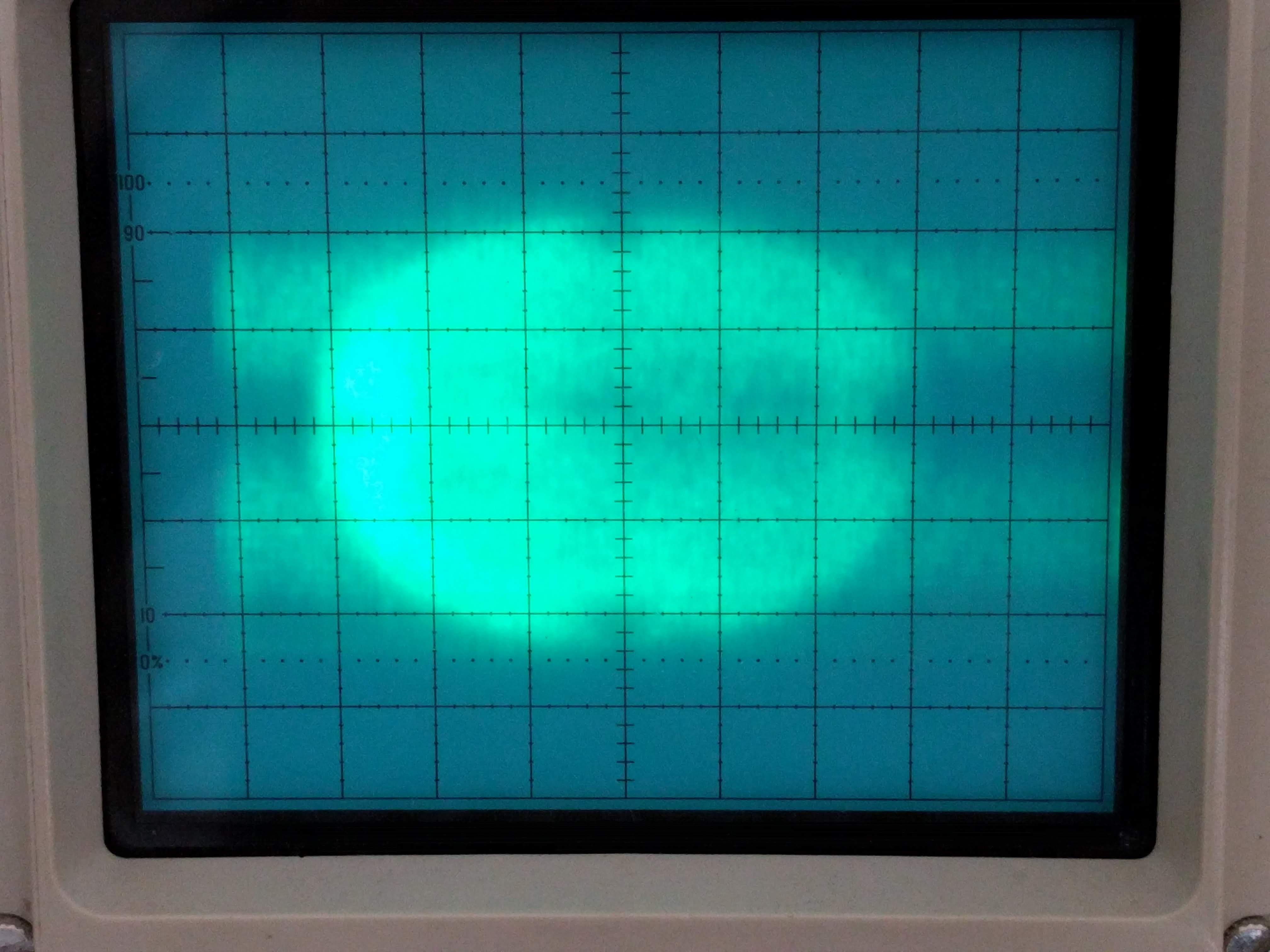
You can see the round shape of the target along with some marks in the edges. The darker bit in the middle are characters, but things are just too fuzzy to see them. Part of the reason was that the video amplifier I used had a gain-bandwidth product of only 4.5MHz. In a non-inverting amplifier circuit with a gain of 100, the bandwidth was only about 45KHz! This just was not enough. There was also some distortion in the deflection amplifiers.
After adding another gain stage to the video amplifier and rearranging the circuit so that I could drive the deflection plates directly with some function generators, I saw this on my oscilloscope screen!
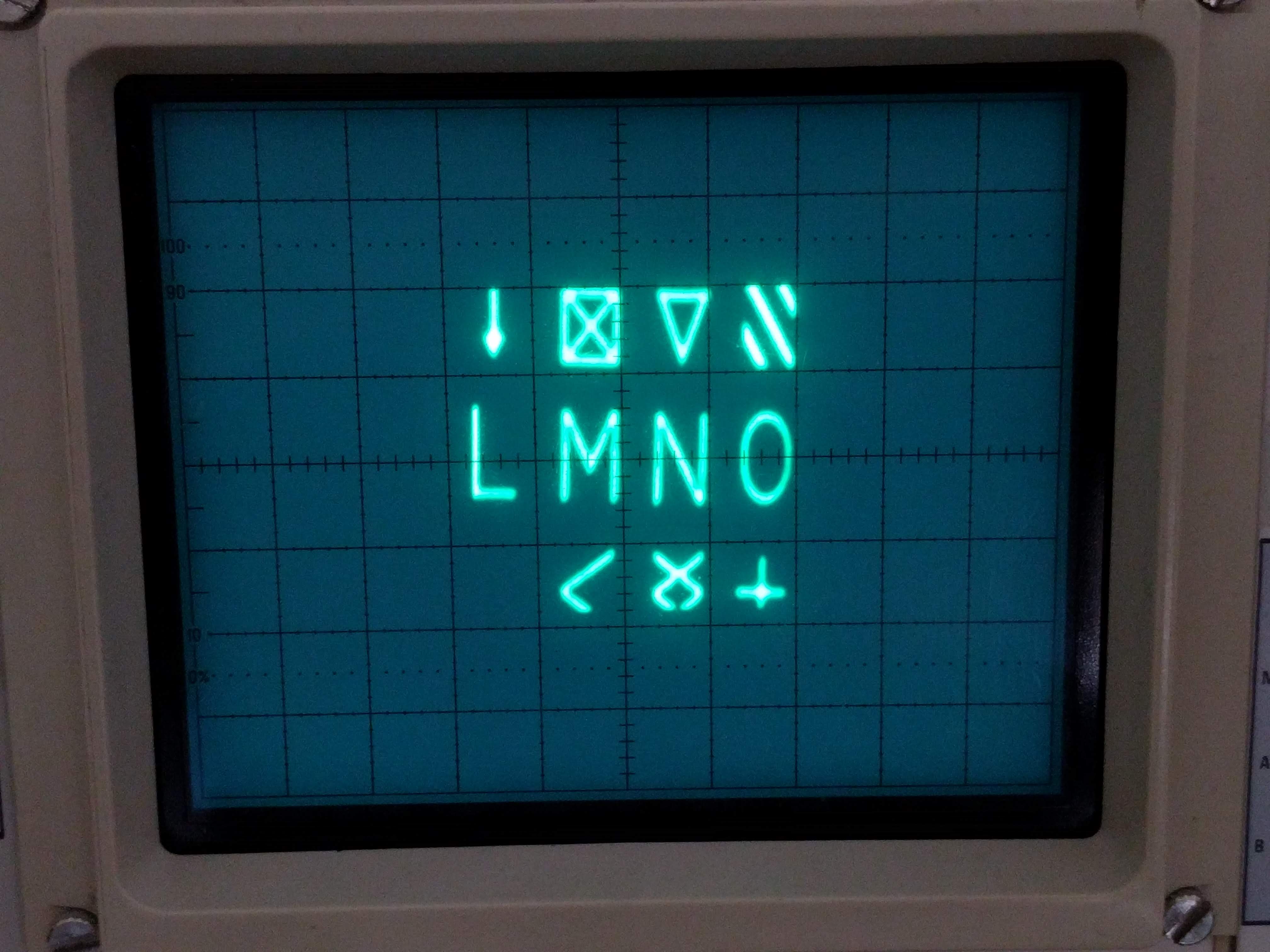
After a little research, I found out that the tube was used in some very early computer terminals including Raytheon’s DIDS-400 (c. 1967). To generate the display, the Monoscope was connected to a standard CRT. There were two sets of deflection circuits: one picked the character from the Monoscope while the other selected the location on the CRT. A pair of sine waves (really!) was fed to both sets of vertical and horizontal deflection plates, producing a raster scan which copied the character from one tube to another.
This worked quite well in the days before character generator ROMs. The tube acts essentially as an analog ROM.
Other companies combined both the Monoscope and the CRT into a single monster tube that had deflection plates, a mask with the character set, and a set of electromagnets that could rotate and position the character on the phosphor screen! Such a tube was called a Charactron(Convair) or Typotron(Hughes). A version of this tube was used in the computer terminals of the SAGE computer used in the US early warning radar system.
I decided to switch back to the higher-voltage deflection amplifiers to see if I could look at the entire character set at once. With the improved circuit, I got a better image:
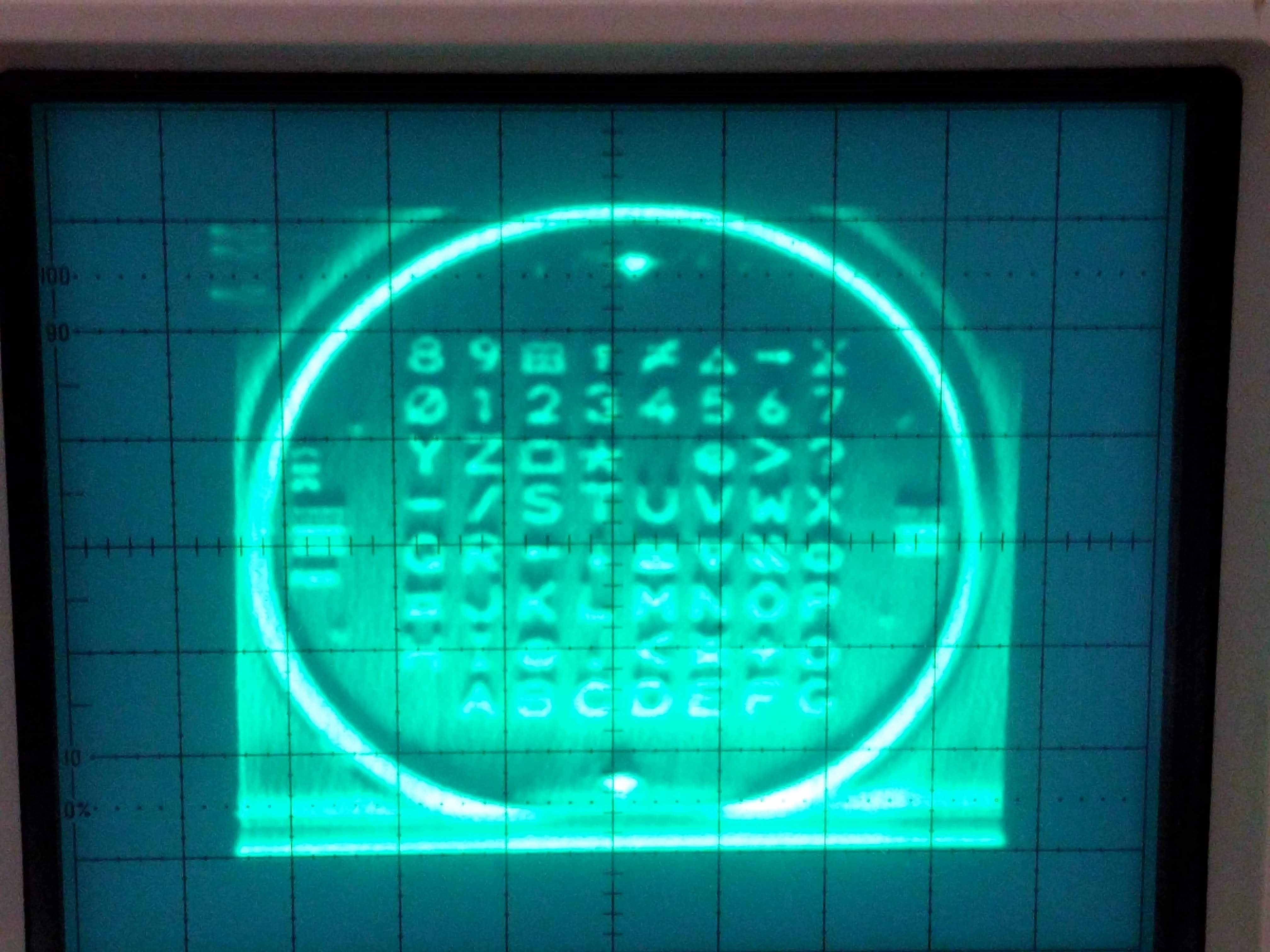
It took a bit of tweaking to get the image. You can see alignment marks and other features on the metal target disk.
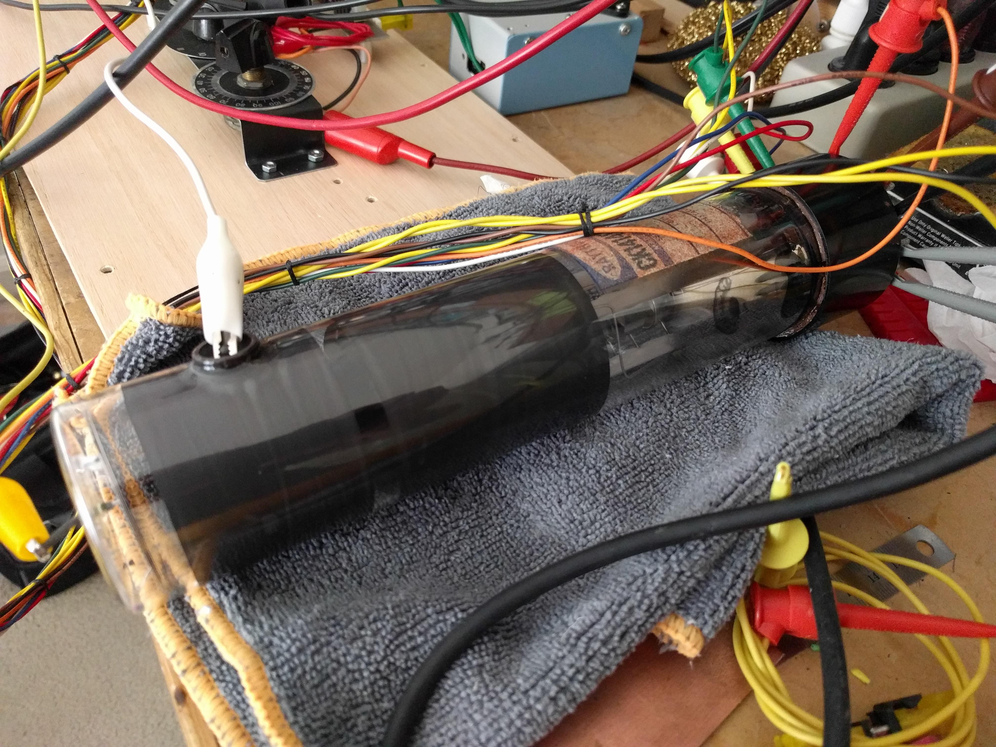
My setup looks like this:
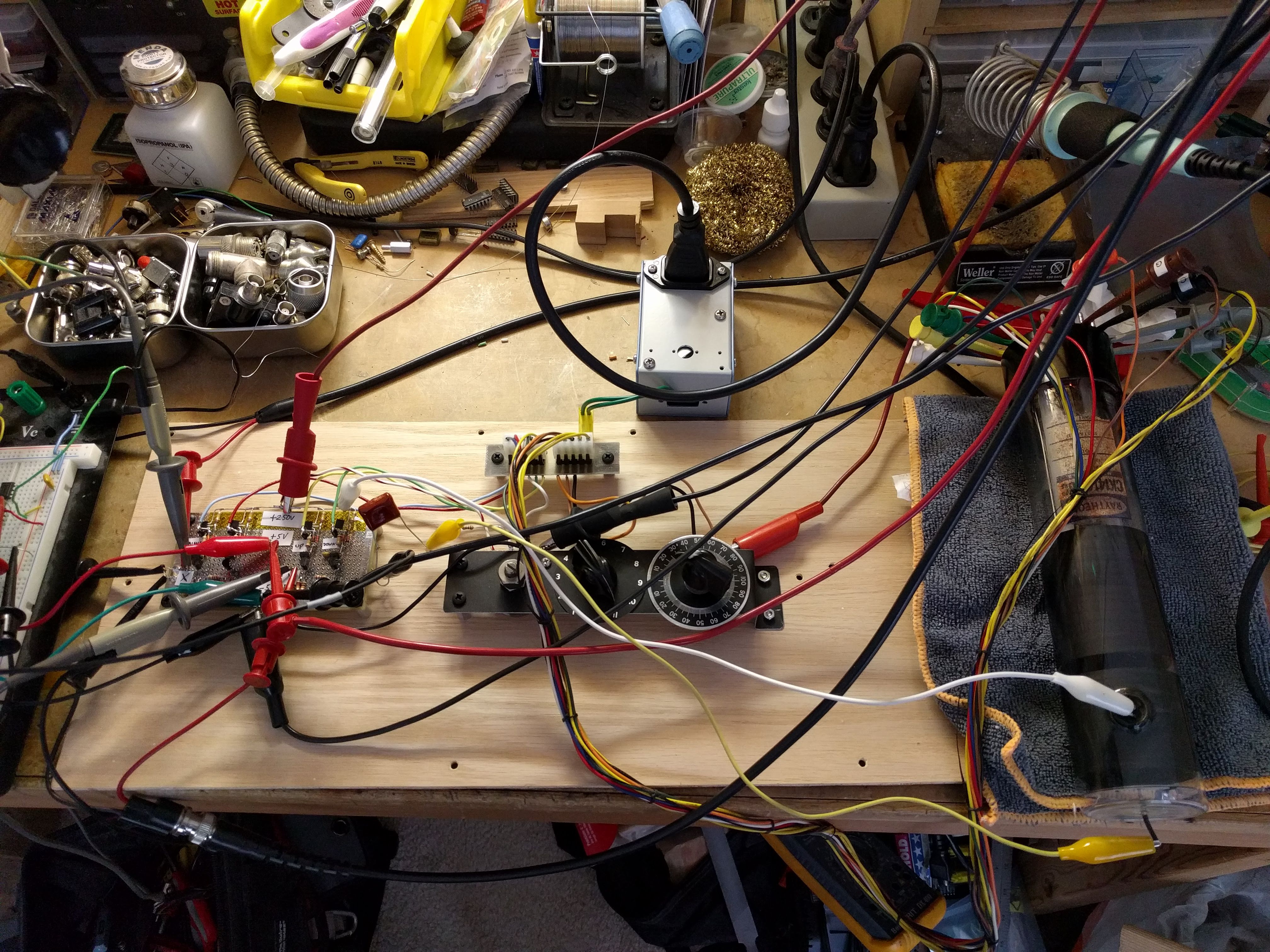
In the middle there are three potentiometers which control brightness (really beam current), focus, and astigmatism.
As I was shutting off the high voltage supply, the image shrank on my oscilloscope screen since the deflection factor decreased, and I saw something interesting:
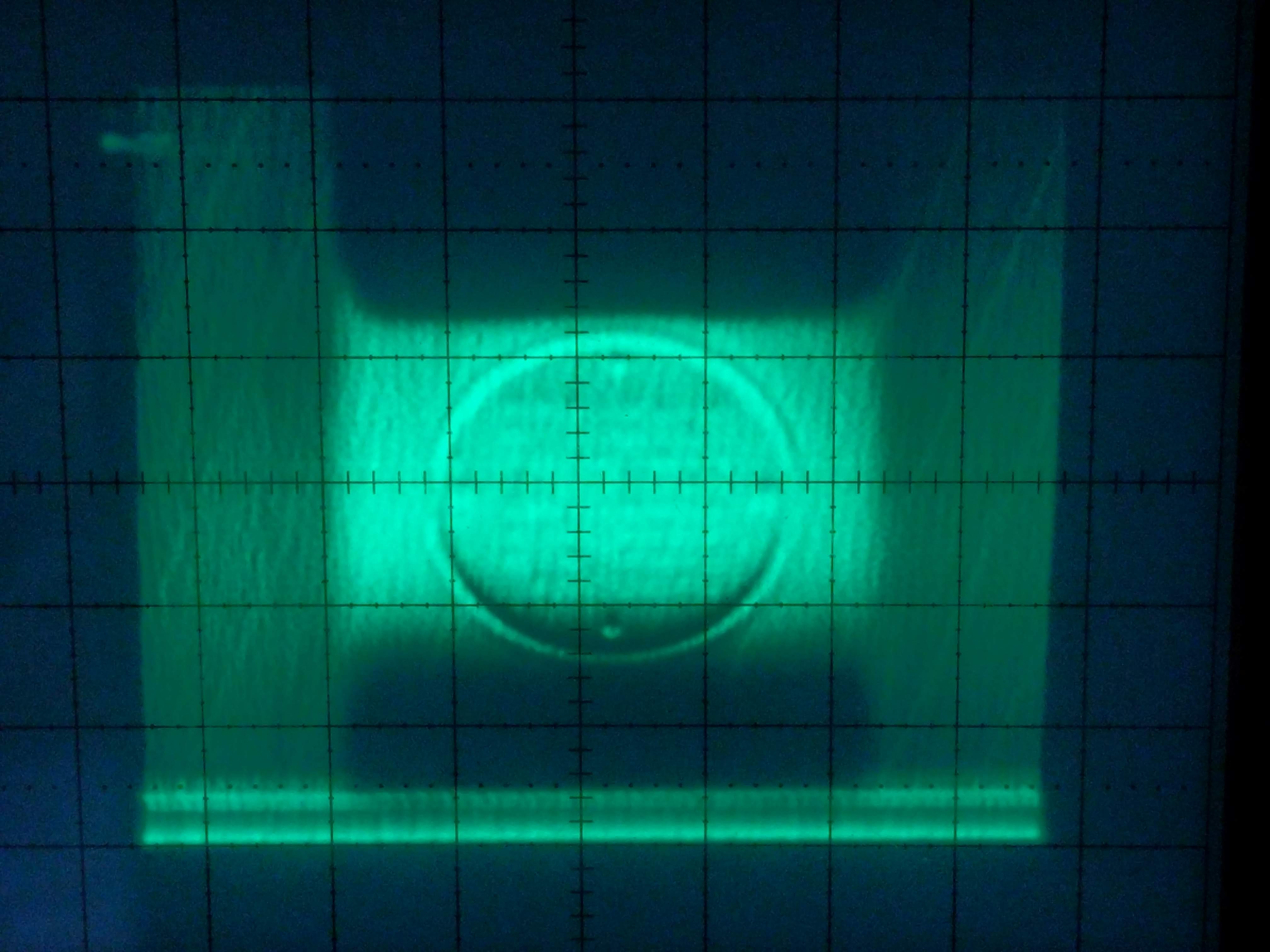
The target is in the middle, but there are odd shadows on the top, bottom, and sides. These are actually the deflection plates! The left and right plates are nearer to the electron gun so they block the view of the top and bottom plates which are closer to the target. When I saw this, I realized that this tube is essentially a miniature scanning electron microscope–only there’s just a single, permanent sample since the tube is sealed.
If you have one of these tubes and you want to experiment, the circuit I used looks like this (click for larger version):
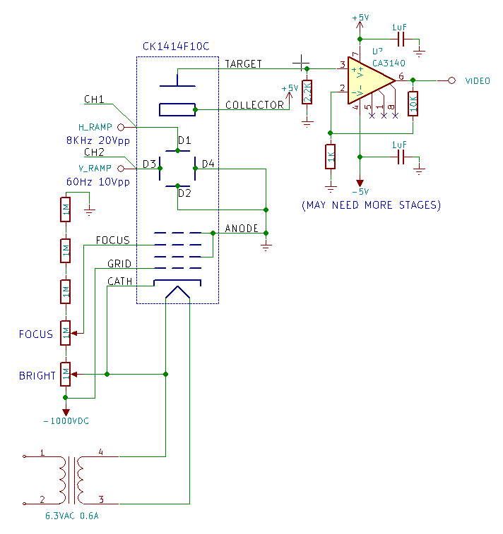
You will need a 1000V power supply such as one designed for operating a photomultiplier tube. Needless to say, high voltages can kill you and should be treated with respect; please take proper precautions when experimenting with this stuff. Ground the metal cases of the potentiometers or use insulated knobs so you don’t shock yourself.
Connect the oscilloscope channels 1 and 2 (in XY mode) to the deflection plate inputs. Connect the oscilloscope’s Z-axis input to the video output from the amplifiers. I’ve only shown one stage, but you’ll need more gain to get a good signal. The function generators should be generating rising ramp sawtooth waveforms, but even sine waves will work. If you can synchronize the two, then you’ll get a more stable picture.
The vacuum tube’s filament needs 6.3VAC, so I’ve provided that with a transformer. Please check the transformer’s datasheet to make sure it can withstand the 1000V between the primary and secondary. Often this is called out as the maximum isolation voltage.
Well, there you have it–when ROM chips didn’t exist, people stored data in miniaturized scanning electron microscopes!
It’s been a while since we’ve had an update to the MOnSter6502 project–we’ve been very busy getting the second revision ready. At the same time, I’ve been designing a simple yet powerful 6502-based computer that can operate at the slow clock speeds required by the MOnSter6502.
But before I go into detail about that, take a look at this video update. It’s one thing to see photos of the MOnSter6502, but the video really brings out just how awesome this thing is in person! (Shameless plug for Maker Faire Bay Area 2017 where you should come visit us.)
The MOnSter6502 runs up to about 60KHz clock, which is quite a bit slower than the original. The computer I’ve designed for it uses another microcontroller to simulate hardware peripherals, inspired by capabilities of various ’80s computers and gaming consoles. The idea is to offload CPU-intensive video and sound tasks to the microcontroller, freeing up the 6502 so that it can be used in real time despite the slow clock.
Right now, I’ve implemented several software-defined peripherals
The computer can also run a full validation suite on the connected 6502, which has been quite useful troubleshooting the highly complex MOnSter6502 boards.
The computer is still a prototype, but you can see some shots of it in the video above.
You can find more updates and information at the project site.
The MOnSter6502 will be at the Bay Area Maker Faire this year! If you’re around, come by and say hi.
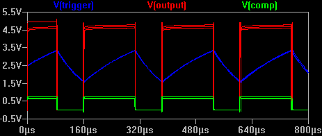
A customer recently asked us some questions about the Three Fives discrete 555 timer kit. One in particular really got my attention.
What is the difference between the National Semiconductor LM555 and the Signetics NE555 timer ICs? Well, the Signetics part certainly came first and the National part was a second source, but the customer noted that The 555 Timer Applications Sourcebook, on page 5-31, states
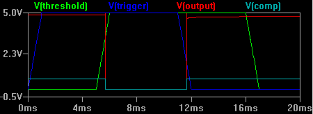
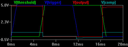
…Table S-2 points out that the threshold overrides the trigger for the type LM555H (National), but the threshold is overridden by the trigger for the type NE555V (Signetics).
Let’s compare the two. First, here’s the NE555 schematic (click for larger versions).
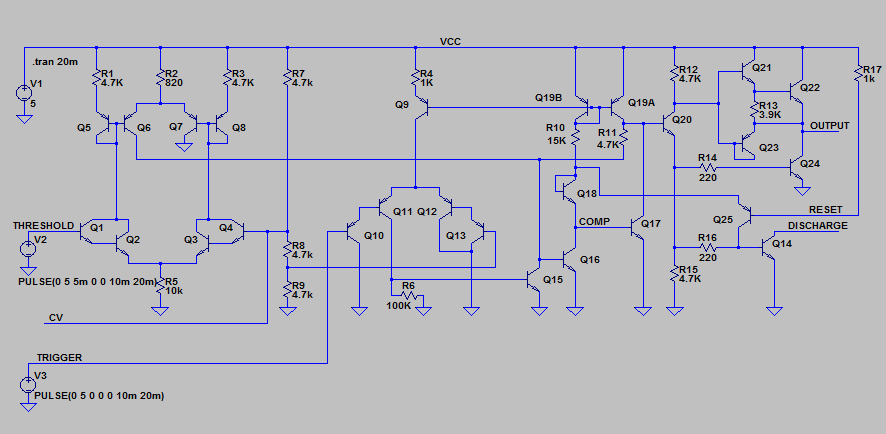
And here’s the LM555 schematic. I’ve kept the component numbering consistent with the NE555 datasheet rather than National’s datasheet to make comparisons easy.
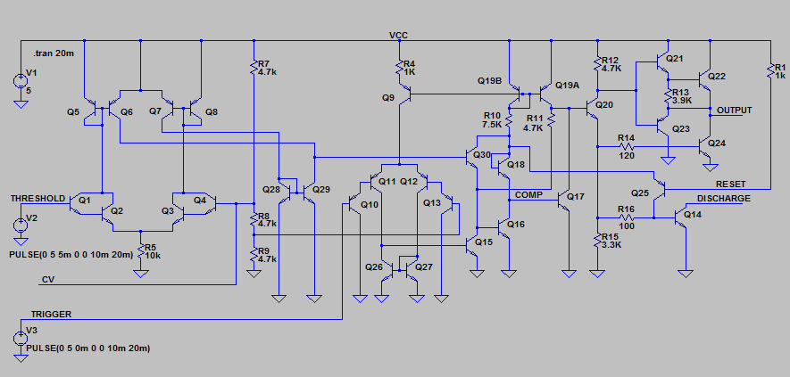
The LM555 makes three minor changes to the timer design:
The most interesting changes are the first two. How do these changes reverse the priority of the two comparator inputs?
The original NE555 gives priority to the trigger signal because transistor Q15 can always overpower the current coming from Q19A and Q6.
Inspired by commenter Katemonster, I’ve put together a short clip with a couple of CRTs from my collection, demonstrating various types of phosphors. There are charts out there that talk about persistence using vague terms like “medium” (compared to what?), so it’s nice to see a real video showing what such a CRT actually looks like.
For the video I’ve used my “orbiter” demo that uses Newton’s law of gravity and Newton’s 2nd law of motion (F=MA) to generate simulated planets that orbit around a sun. It’s a nice way to demonstrate persistence (the way the phosphor fades as the electron beam moves away).
P1 Phosphor
This is the basic green phosphor. At 525nm primary color wavelength, it looks slightly more blue than common super-bright green LEDs. The chart linked above lists the persistence time as 20ms which seems reasonable. The formulation for this phosphor varies between manufacturers so some tubes might be slower than others. It’s very common in early oscilloscopes and oscillographs, and apparently some radar systems as well.
P2 Phosphor
The P2 phosphor color has even more blue in it than the P1–it’s very close to “stoplight green”. The persistence is much longer as you can see in the video (30 seconds or more, depending on the ambient light levels). The charts and reference documents I have list the primary applications as oscillography and radar.
P7 Phosphor
P7 is a very interesting phosphor. It is a cascade phosphor, meaning that it has two layers of material. The electron beam strikes the first (outer) layer which emits a bright blue light with some light near ultraviolet. This high energy light excites the second layer (inner, in contact with the glass) which is a much slower material that emits a yellowish-green light with a very long persistence (around a minute). In the video I move the “orbit” trace off to the side so you can see that original afterimage persists.
It was used mostly for radar and sometimes in oscilloscopes to capture one-time events before storage tubes were invented.
So why use a cascade phosphor? One source states that it was originally designed to be used in intensity-modulated displays (varying brightness levels), but it turns out it also helped prevent radar jamming. Since the jamming signal was not synced to the radar pulses, a long persistence phosphor could average out the jamming signal and allow the operator to see the true signal as viewed on an A-scope (time-based pulse waveform monitor). [Cathode Ray Tube Displays, MIT Radiation Laboratory Series, pg. 626]
P12 Phosphor
This one is my favorite. It’s an orange medium-persistence (a few seconds) phosphor that was apparently used for radar indicators. I don’t know of any that were used in oscilloscopes.
P31 Phosphor
The P31 phosphor was invented as an improved P1 phosphor. It’s much brighter (P1 is 32% as bright) and has short persistence (<1ms). The color has a bit more blue in it–in fact, very close to the P2 phosphor’s color. I would say most analog oscilloscopes from the 70s to today use CRTs with the P31 phosphor.
In many cases these CRTs would be installed behind a colored piece of plastic acting as a color filter. For example, P7 CRTs were often installed with an orange plastic filter in front to make the blue/white phosphor look more similar to the secondary yellow phosphor. P31 CRTs usually have a blue or green plastic filter.
For further reading:
Take a look at my crt-driver GitHub repository. I tidied things up a bit and more importantly, released the Altium project files, schematics, boards, and even the output job file. It’s all licensed under the Creative Commons Attribution-ShareAlike 3.0 license. Read the Creative Commons page for the full terms, but basically you can share or adapt any of it as long as you give me credit (a link to this blog would be appreciated) and make sure that you keep the same license so that others can do the same.
If you don’t have Altium (expensive, closed source), you can at least open and edit the schematics with CircuitMaker (free, closed source, limited). Sadly, CircuitMaker will not let you edit the Altium PCB layout.
On Saturday I found a deuterium arc lamp at a local surplus store. It was used, and most likely pulled from an ultraviolet spectroscopy machine. I could not find data on the specific lamp model, but I found a similar lamp. On the chance any of you might know what it is, the lamp is marked
D 805 K
56066349
West Germany
H9
Before running any tests with the lamp, I wiped it down with isopropyl alchohol to remove any fingerprint oils. When heated, they can cause the glass envelope to bubble and even melt, destroying it.
To run this lamp, which is a gas-discharge type, you first have to heat up the cathode. There is a very thick double-spiral tungsten filament inside that uses 2V at 4.5A (or 9 watts!). Once it’s warmed up for a minute or two, you apply the high voltage to the anode. I connected it to a current-limited electrophoresis power supply set to 50mA. The lamp started at 350V and settled to an operating voltage of about 84V. Incidentally, the heat generated by this helps keep the cathode hot, and the filament current can be reduced to improve its lifetime.
Here’s a quick video showing what it looks like.
Deuterium is an isotope of hydrogen: hydrogen has one electron and one proton, and deuterium takes that and adds a neutron. It is not a radioactive isotope, unlike tritium, which has two additional neutrons. According to Wikipedia, Deuterium is used in these lamps because it emits more UV with a wavelength less than 400nm.
If you’ve got one of these lamps and you plan to light it up, you’ll need eye protection. I ran it at a very low beam current (most likely it was designed for 300mA!) and the light was not so intense, but you might want more than just a pair of sunglasses if you’re going to full power…