
Laser Printer Scanning Mirror Experiments
August 4, 2008 9:49 pm ProjectsDigging through my junk box today, I unearthed the scanning mirror from a laser printer, otherwise known as the Heart of the LaserJet. It’s got the infrared laser that generates the image as well as the scanning mirror that creates the raster. It’d be fun to get it up and running for nefarious purposes…
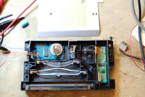
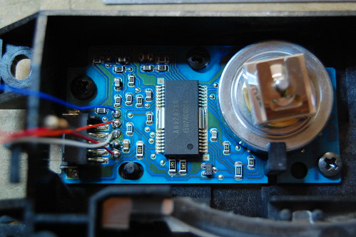
The scanning mirror and motor uses a “custom” (undocumented) Panasonic motor driver, the AN8247SB. As usual, Google returns a million hits for grey market parts brokers who spam the keywords with things like “PDF” and “datasheet” without offering any actual information.
So my usual plan of attack does not succeed.
The second step is to examine the single 5-pin connector to see what I could figure out. Pin 3 is obviously ground because it is the only pin connecting to any large ground planes. What I suspect to be pin 5 appears to be the power supply since it connects to two very low valued resistors (0.75 total) which probably perform a current sense function. Most of the other pins disappear inside the undocumented chip.
Digging around in my junk box produced the power supply board for the laser printer. I was able to find the other side of the connector and quickly verify that pin 3 is indeed ground. What I thought was pin 5 is actually pin 1, and it is indeed power. Tracing back through the power board I notice that it connects to a filter capacitor with a 25V rating. Based on that I conclude that it is very likely a 12V rail. I soldered some jumper wires onto the board and began experimentation in earnest.
Connecting the board to 5V didn’t result in any excessive current, so I slowly ramped up the voltage to 12V. Nothing happened. Not even anything bad.
Looking carefully at the laser printer’s power supply board, I traced the other three connections. They all went into a big microcontroller, but the wiring connections were different. Pin 2 had a 10K pullup to some low voltage supply, pin 4 went straight into the microcontroller, and pin 5 came from an RC filter from the microcontroller.
First I tried connecting a 10K pullup resistor to pin 2 on the motor driver board to 3.3V, and I hung a scope probe on it. It was a logic low. I spun the mirror assembly, and I saw pulses! This must be the tach output. By rotating the mirror very slowly by hand, I counted 6 pulses per revolution.
Next I probed the voltage on the other two pins, which were both weakly pulled up to about 3.6V on the motor driver board. I pulled pin 4 low, and the tiny mirror spun up with a whine to about 13,000 RPM (as measured by the tach output)!
That was really great because I was worried that those two pins were I2C control lines which would have made reverse engineering a lot more difficult. It’s not impossible because you can hook it up to a microcontroller and scan all possible I2C address to see if any slave devices respond, then randomly try to access registers… It gets pretty messy anyway.
The last pin gave me a bit of a headache because grounding it didn’t really do anything. I tried grounding it through an ammeter and noticed that the current, although it started at a few hundred microamps, tapered off quite rapidly. There must be a capacitor in series somewhere on the motor board, and that means the pin is designed for AC signals. Since no signal came out of the pin, it must be an input. I connected a function generator at a few kilohertz with a 3.3Vp-p square wave, and when I turned on the motor, I noticed that it “cogged” a lot and generally had a hard time. On impulse, I dramatically increased the frequency. Suddenly the motor slowed down and settled at a constant speed. By changing the frequency, I could manipulate the motor speed.
So pin 5 is a synchronization input. I guess the RC filter on the microcontroller side was designed to help reduce EMI in the cable. The next step was to figure out the relationship of input frequency to output speed, so I connected my trusty old Nixie frequency counter to the output of my function generator and my multimeter (set to frequency) to the tach output. The ratio appears to be fixed: divide the input frequency by 136.6 and you’ll arrive at the RPM of the mirror.
Here’s the complete pinout:
1 – +12V
2 – Tach output (open drain, 6 pulses per revolution)
3 – Ground
4 – Enable (active low, so drive it low to turn on the motor)
5 – Synchronization input
Now it’s time to come up with projects…
Just to give you a hint, I have something in mind involving a photomultiplier tube.
Drop me a line in the comments if you think you can guess what my idea is, or to post your own ideas, or even if you find this information useful for your own project.
vedat kaya :
Date: November 1, 2008 @ 3:01 pm
Its very interesting i was thinking to use of this motors for demo show helicopter project. Because i have a lot of scanner motor from old laser printers. I was busy with datasheets and other tips. your tips helped me a lot thanks but can you show or send to my email with scheme for more explanations?
Ragards.
Colin :
Date: December 30, 2008 @ 2:51 pm
I have just dismantled my canon lbp660.
identical laser assemblies.
wired up as shown and works ok (down to 5v)
My plan is to replace laser with a visible type and output a scanned picture (from a pc or pic chip)
this will also need an external mirror (more work!)
jy 1 :
Date: January 8, 2009 @ 5:47 am
afer a few test i see you counted the pins from left to right. right?
jy
D. Sornadurai :
Date: January 11, 2009 @ 11:24 pm
Dear Sir
The information you have provided is really good. Similarly I opened up a scanner assembly in a Laser Printer and I found there was six connection coming out of it. I could not identify the connection from the chip TB6514 -F. Could you please try it also and send a mail regarding this chip. It will be very useful for servicing my printer.
Abend :
Date: July 25, 2009 @ 10:53 am
I have a laser scanner head from an HP laser printer that uses the TB6514F chip. On my scanner, pin 5 of the connector is ground, pin 1 of the connector is 12V+, and pin 2 must be grounded to spin the motor.
Connector Pin – Chip pin as follows:
1 – 3
2 – 7
5 – 6 (cooling fins)
Surajit :
Date: February 19, 2010 @ 1:44 am
Hey we got a strange method to rotate the motor!
the motor driver for our scanner is the same panasonic chip but the connection is entirely different! so we connected the pins 4 and 5 which are shorted to the +12V supply and when we touch another wire connected to third pin with our hand, the motor starts rotating but if we connect it to ground nothing works Can anyone explain why this is happening.
Douglas Berlier :
Date: April 22, 2010 @ 7:06 pm
I am looking at using this item for a BORG costume! (1) I just want the motor to spin. (2) changing its velocity would be COOL! (3) what did you say the pinouts were again? 3 is ground!
which pin is voltage?
visually… closest to screw or closest to board edge?
Daniel :
Date: April 23, 2010 @ 9:54 pm
I have one of the mirror boards out of a 4P with the TB6514 controller. I found a doc on a similar chip (similar series number and this is OEM so probably related) on the Toshiba website.
http://www.semicon.toshiba.co.jp/docs/datasheet/ja/LinearIC/TB62206FG_ja_datasheet_080314.pdf
Douglas Berlier :
Date: April 27, 2010 @ 9:53 pm
well that helps out a lot! Here we go! the pinouts given in the original text is correct. i did the same and checked the voltages coming from the power board and going to the controller through the 5 pin connector. On the motor board the pin 1 is closest to the right side of the board with the connector at the bottom. I connected ground to pin three, 12v to pin one and I connected pin 4 to ground to pull it low and the motor spun like a charm. It also spins at lower voltage in as well.
One thing i would like to do is proceed the motor. No matter what speed it spins I seem to still get a “still” square miror. i want the mirror to slowly move forward in order to have a laser beam travel as a dot along a projection instead of just having a straight line projected on a wall. anyone? anyone?
Koney :
Date: January 17, 2011 @ 7:00 am
nothing new? What about chances to use arduino for controlling this motor?
gr00ve :
Date: January 29, 2011 @ 12:18 am
You could have found pinout easely from a chip datasheet, which is next to connector.
I have the same unit, but my interest was on the other side of the box. the IR laser. I was trying to power it up, but no success. if anyone has some ideas — please let me know on the mail!!
elerepair[at]gmail[dot]com
Douglas Berlier
this motor spins too fast for You, to be able to get a visible, moving dot. I suggest You to use a stepper motor or something, with this square motor. And make stepper move forward, and back, or just spin one direction, to be able to see a dot moving along the line.
kalifdddd :
Date: February 7, 2011 @ 2:45 am
Hello.I have the same motor and it doesnt work.Could you draw schematic please .
Ryan :
Date: April 1, 2011 @ 12:59 am
Great post!
I had a laser head I pulled out of a Sharp (I think) printer. It also had a 5 pin connection to the motor, but the pin-out was different:
1) +12V (just a guess)
2) GND
3) Enable (pulled up, active low)
4) Probably output from the opto encoder I see on the board, but so far nothing
5) Sync (pulled up, active on either edge, it seems)
The motor will not spin up without the sync signal, and it seems happiest with something around 380Hz. The controller on the board was marked “NBC3109”.
Carl :
Date: April 6, 2011 @ 4:49 am
Hi, I have the same chip, but on a different board from a different printer. There also is a 5-pin connector, but it definitely has a different pinout. Only the AN8247SB is the same. Could you map your input ports to pins on the 8247 so it is easier for other people to find out the pinout of their PCBs? Thanks!
Lars :
Date: May 17, 2011 @ 3:23 pm
I have almost the same circuit. The same controller but another layout. My pins are from right:
1 – +5 V
2 – ??
3 – GND
4 – Enable
5 – Control
I experience that my control pin is not frequency controlled but rather the duty cycle controlled the motor speed. Using a frequency of 5 or 50 Khz did not change the motor speed. Changing the duty did.
Good work.
Regards, Lars
Lars :
Date: May 17, 2011 @ 3:28 pm
Oh, and my guess of what your project is about is to build an IR-camera. If so, I would like to build one too.
Regards, Lars
Manu :
Date: July 15, 2012 @ 6:18 pm
Years after, your explanations were very useful to me after dismantling a very old laser printer and trying to powering up the scanner unit. My 200mw green laser can now draw a straight line! Thank you!
steve :
Date: October 3, 2014 @ 12:21 am
hey i want to use the controller with an arduino uno. help.
Maciek :
Date: February 21, 2018 @ 9:14 am
12V? That is unlikely. Motor and solenoid power supply voltage in all HP (Canon) printers is 24V.
After all you can just take your multimeter and check 🙂
Service manual for the HPLJ8000 gives following description of the scanner motor connector (may be different in the model you have):
1: 24V
2: GND
3: SCNCLK – scanner motor reference clock signal
4: /SCND – L to drive motor
5: /SCNRDY – L indicates motor reaching the precscribed speed
Good luck in building your CTF/CTP.