
555 Contest Entry
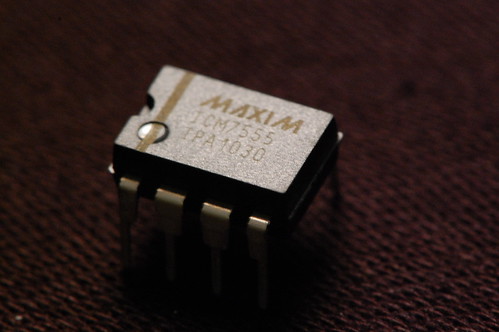
February 23, 2011 10:19 pm ProjectsYes, it’s not really vacuum tube related, but I built an entry for the 555 timer contest. It uses an ICM7555, which is Maxim’s second source of Intersil’s CMOS version of Signetic’s original NE555 timer. Turns out the fact that it is CMOS is important for this particular circuit…
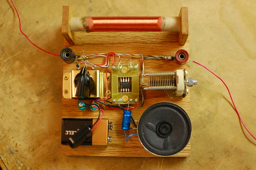
My entry is an AM radio. The only active device (silicon, germanium, or otherwise) is the ICM7555. The tuning is accomplished with an inductor and a capacitor, and the ICM7555 acts as an AM demodulator and class-D power amplifier to drive the speaker.
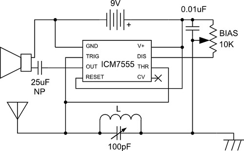
You may be wondering how all this is accomplished with a 555. The schematic is below.
Here’s how the circuit works: The AM radio signal is tuned by inductor L, which is 300 turns of wire on a 1/2 inch diameter cardboard tube made out of an old toilet paper roll, along with the 100pF variable capacitor. One end of the parallel configuration of L and C connects to an antenna (surprisingly long!) and the other end connects to a ground wire which is tied to the AC outlet ground (old books tell you to ground it to a water pipe). So far this is exactly like an AM crystal radio.
The 555 timer is configured as a pulse width modulator in a non-traditional configuration. If I used the standard approach and connected the input to the CV pin, the low impedance of the pin would prevent the circuit from receiving any radio signals. I had to invert the circuit and tie both high impedance analog pins, Threshold and Trigger to the radio signal input. This is the reason why the CMOS version of the 555 timer performs much better than the standard bipolar, which has higher input bias current.
The pulse width modulator ramp is created by the 0.01uF capacitor and the 10K bias potentiometer which are connected to the Discharge pin. The potentiometer wiper goes to the LC arrangement. With no radio signal coming in, the voltage on Threshold/Trigger ramps up until it hits the threshold, and then Discharge causes the voltage to ramp down again.
When a radio signal comes in, it gets superimposed on the ramp signal, causing the threshold and trigger comparators to trip early or late in a cycle. This variation causes the output duty cycle to vary, which we can hear as sound in the speaker.
Demodulating the signal properly requires adjustment of the bias knob, so that part of the radio signal is “clipped” and ignored by either the threshold or trigger comparators. This ensures that the negative “halves” of the radio wave don’t cancel out the positive “halves”.
Want to hear what it sounds like? Check out the video below:
And of course, I can’t end the post without a gratuitous shot of the ICM7555 in circuit.

Very cool! :
Date: February 25, 2011 @ 1:51 am
Wow! I wish my own projects could look as neat and be as innovative as this one. Great work! Well executed!
/Anders, Sweden
SockThief :
Date: February 25, 2011 @ 6:15 am
Hey Eric,
really awesome project, not only unexpected use of a 555 (I would never have thought of it, that’s for sure) but it’s an incredibly beautiful construction.
Is it possible to request a follow-up blog post on this? You briefly touched on the circuit design and the importance of the CMOS version of the 555, but I’d love to read some more on it.
Cheers!
Olivier :
Date: February 25, 2011 @ 6:52 am
Hi Eric,
I think your design is incredibly awsome ! The small distorted sound is doing so well with the wood and wires design.
It is very far away from 555 use. I have made many odd things with it but not what you did.
It is so bluffing that I hope you will win the contest.
Kind regards.
Scott Harden :
Date: February 25, 2011 @ 8:01 pm
Very clever! I’m impressed! As a note to newcomers, be very wary about thinking of AC ground as “near to earth ground”. In the RF a good ground is just as important as your antenna, and who knows what else AC ground is used for! Lights, other electronics, air conditioners – all sorts of things tie into the same wires which may push noise back into your radio. Living on the 2nd floor of an apartment, my AC ground is noisy as can be! I have a radial system of balanced dipole antennas hanging on my ceiling inside my apartment to try to avoid using AC ground as ground. Also, that variable capacitor is expensive and a little hard to find (I know!) – a configuration with a varactor diode and potentiometer would be cheaper, easier to access for anyone to recreate, and allow voltage controlled (microcontroller?) tuning. I use power rectifier diodes successfully for this purpose! Food for thought… but again, awesome project. You really nailed the heart of the competition!
eric :
Date: February 26, 2011 @ 3:04 pm
Thanks Scott, you are right about the AC ground. The tuning capacitor was in my junk box. Any cheap variable capacitor would also work.
Norbert :
Date: March 29, 2011 @ 4:26 pm
Hi Eric!
The construction is very super, but your schematic diagram is wrong. (If I good think, this content two errors.)
1., The treshold (pin6) not comon the trigger (pin2). The trigger connect the antenne and paralel resonant circuit. The treshold connect the timer tags. If not connect, then this circuit timing is nothing.
2., The timer 0.01uF you connect VCC and GND. The cap is charged _once_ and…? 🙂
A think, the cap and potmeter serial connection. Common point the cap&pot connect the discharge (pin7) and potmeter mid point connect the treshold (pin6)? My friend testing tomorrow this modifications.
If my idea is good, then please correct the scheme. Thx., best regards: Norbert Kis (Hungary)
JD :
Date: March 30, 2011 @ 1:31 am
The circuir, construction, shamless plug for Maxim, and VIDEO, are all AWESOME. I love the almost subconcious snipits in the video. How was it produced. Who is the producer ? Anyway … You have a nonlinear ramp, your audio will distort at any volume. I suggest you impliment a Threshold Optibias current source, then check the noise performance against a differential reference. Anyway …
Thinking outstde the box to solve practical issues gets Eric my vote as #1 555 application. Even the inventor of the 555 topology and original IC was impressed with this innovation,
How many uH is the L, range of C => 1/2*pi()*sqrt(L*C) => Tuning range.
This appears to be a direct conversion topology, unless the pointer on the pot is really a germanium diode. Where is the signal detected ?
mukesh harsh :
Date: April 21, 2011 @ 11:13 am
is there possible to carry video signal in such circuit?
Dave B :
Date: April 21, 2011 @ 12:28 pm
@Norbert:
I thought the same as you did, but just realized my error. The .01uF cap is sequentially charged and discharged through the pot, so long as the output is switching between Hi and Low, which alternates driving pin 7 (Dis) to battery return, pin 1. The ground on the other side of the cap is not tied to battery return, but to Earth ground AND to the low side of L, therefore (at DC or Audio frequencies) to Trig and Thresh!
VERY clever design!
Dave
shane maxfield :
Date: June 22, 2011 @ 7:20 pm
10 years ago i made this 555 radio.
Steve :
Date: July 24, 2011 @ 9:13 pm
It seems that this is operating at about 33 MHz to 50 MHz maybe. 100pF and the 1/2 inch air core inductor of 300 turns comes in about 230nH maybe. That would be Fire, Government, Police band kind of stuff.
What did you hear?
Rick Herndon :
Date: October 4, 2011 @ 3:50 pm
A ham radio friend commented quite completely on this project. He gave permission to forward it here:
==
Using a MAXIM ICM7555 as an AM broadcast band receiver is innovative indeed!
The amount of ICM7555 device capacitance that adds to the 100 pF air-variable tuning capacitor is
negligible, and the antenna-to-earth capacitance also is negligible. Ignoring these negligible
capacitances, the resonate frequency exhibited by the 100 pF air variable tuning capacitor and
the inductor is what determines the tuning of the AM receiver.
I believe the inductor is poorly dimensioned. From the description and the picture, I estimate
that the inductor has 300 turns of #33 enamel-coated wire, in a single-layer solenoid form of
0.5071 inch wire-center-to-wire-center inductor diameter, close-wound over a 2.367 inch length).
As such, the inductor has an inductance of about 223µH. With the variable capacitor set to
full-mesh at 100pF, the resonant frequency is 1066 kHz and this is the low frequency limit of the
tuning range. Assuming the unmeshed value of the variable capacitor is 9.6pF, then the high
frequency limit of the tuning range is 3440 kHz (reaches the 87 meter band). Aside from
exhibiting insufficient inductance for the tuning range of the AM broadcast band, the inductor
has low Q. The description of the inductor, “300 turns of wire on a 1/2 inch diameter cardboard
tube made out of an old toilet paper roll”, constrains the Q to be low because the excessive
ratio of length to diameter of the inductor (about 4.668:1) precludes the obtainment of high Q.
What to do, what to do?
I suggest replacing the original inductor with an alternate inductor that uses an ordinary 1.75
inch diameter toilet paper roll as its form. The increase of form diameter, from 0.5 inch to
1.75 inch, is beneficial for obtaining greater inductance and for obtaining greater Q. Instead
of #33 enamel-coated wire as used in the original inductor, an alternate inductor made of #28
enamel-coated wire or an alternate inductor made of #26 enamel-coated wire is suggested. See
table below for the inductor specifications, and compare the original inductor with the two
suggested alternate inductors: Alternate 1 and Alternate 2. Unlike the original inductor, both
of the alternative inductors provide essentially complete tuning range coverage of the AM
broadcast band.
+—————————-+————-+————-+————-+
| Inductor specifications | Original | Alternate 1 | Alternate 2 |
+—————————-+————-+————-+————-+
| Wire gauge | #33 | #28 | #26 |
| Wire total length (inches) | 478 | 1124 | 1309 |
| Wire thickness (inches) | 0.0071 | 0.0126 | 0.0159 |
| Form diameter (inches) | 0.50 | 1.75 | 1.75 |
| Inductor diameter (inches) | 0.5071 | 1.7626 | 1.7659 |
| Inductor length (inches) | 2.367 | 2.761904762 | 4.013605442 |
| Inductor length/diameter | 4.667718399 | 1.566949258 | 2.272838463 |
| Numer of turns | 300 | 203 | 236 |
| Inductance (µH) | 222.9460301 | 900.3075203 | 903.0426128 |
| Resonance with 100pF (kHz) | 1065.909321 | 530.4258643 | 529.6219909 |
| Resonance with 9.6pF (kHz) | 3440.207540 | 1711.942116 | 1709.347624 |
+—————————-+————-+————-+————-+
Note that the “Inductor diameter” specification includes the “Wire thickness” in addition to the
“Form diameter”. In other words, “Inductor diameter” amounts to the wire-center-to-wire-center
distance.
73 to K5FNI de WD8PNL, -= Ron Wiesen =-
==
Note: in order to read the table, you may have to block and copy it out to a wider display than is possible here.
Rick Herndon :
Date: October 4, 2011 @ 3:51 pm
Ahh, I see that the font here is not monospaced like Courier. If you want to see the table above, you will have to block it and print it out in a monospaced font like Courier.
Alex :
Date: December 27, 2011 @ 10:27 am
Ok, it’s cool but if this device works only with external antenna and ground – i prefer to use the 1zh29b tube as a grid detector o regenerative receiver with 9V (plate) and 1.2V (heater). Best regards to all the HAM’s! 73!
Billy :
Date: January 1, 2012 @ 9:55 am
This project seems like exactly what I was hoping for. A simple project to use as a starting point with radio. I have three questions to help me get started.
1) Would it be possible to make a transmitter with a similar circuit?
2) Could a typical 555 work instead of the 7555?
3) Would you consider posting this to instructables with step by step instructions?
Also: I reformatted Rick’s table in notepad with tabs and I’m also posting it in code tags since I think they might use monospace fonts. Lets hope it works!
+—————————-+————-+————-+————-+————-+————-+————-+————-+————-+————-+————-+-————---+

| Inductor specifications 	| Original	| Alternate 1 	| Alternate 2	|

+—————————-+————-+————-+————-+————-+————-+————-+————-+————-+————-+————-+-————---+

| Wire gauge			| #33 	 	| #28 		| #26 		|

| Wire total length (inches)	| 478  		| 1124 		| 1309 		|

| Wire thickness (inches)	| 0.0071	| 0.0126	| 0.0159 	|

| Form diameter (inches)	| 0.50		| 1.75 		| 1.75 		|

| Inductor diameter (inches)	| 0.5071 	| 1.7626	| 1.7659 	|

| Inductor length (inches)	| 2.367  	| 2.761904762	| 4.013605442 	|

| Inductor length/diameter	| 4.667718399	| 1.566949258	| 2.272838463 	|

| Numer of turns 		| 300        	| 203        	| 236         	|

| Inductance (µH)		| 222.9460301	| 900.3075203	| 903.0426128 	|

| Resonance with 100pF (kHz)	| 1065.909321	| 530.4258643	| 529.6219909 	|

| Resonance with 9.6pF (kHz)	| 3440.207540	| 1711.942116	| 1709.347624 	|

+—————————-+————-+————-+————-+————-+————-+————-+————-+————-+————-+————-+-————---+
eric :
Date: January 22, 2012 @ 11:36 pm
Here are some answers to your questions:
1) Maybe. You would need a circuit that oscillates and modulates. Since the 555 is an oscillator, you’re already on the right track.
2) The 7555 is a CMOS version of the bipolar 555. The most noticeable difference is that the 7555 has high impedance inputs while the 555 does not. My radio circuit needs the high impedance to function, so the 555 would not work in it.
3) Hadn’t thought of the Instructables thing. There are some very good beginning radio websites out there that do a good job explaining how to build simple radios, so I am not sure what I could really contribute with my “hack”.
The table didn’t come out, unfortunately. I’ve been meaning to try out a different coil design, but there are so many new projects I’ve been working on…
Billy :
Date: January 1, 2012 @ 9:57 am
Apparently my attempt at fixing the table didn’t work. Oh well.
Eugen Grzondziel :
Date: March 12, 2012 @ 3:27 am
A very brilliant idea, but does it work really as described? (as D-class amplifier) i am not sure. The circuit works as radio WITHOUT capacitor 10 nF too.
eric :
Date: April 4, 2012 @ 10:15 am
old books tell you to ground it to a water pipe
In my house, AC ground goes right to a copper water pipe in the basement.
teddy7 :
Date: June 23, 2012 @ 11:04 am
What diameter wire are you using with the 555 Radio. Will #30 CuEn work,
or did you use another size?
eric :
Date: September 16, 2012 @ 4:16 pm
To be honest, I can’t remember. If you have #30, then use it. The current is really low so there’s no problem.
Steve Greenfield :
Date: October 31, 2013 @ 7:12 am
I think you must have made a mistake in your schematic. As it is show, the 0.01uF cap is merely connected from +9V to ground, and will not otherwise interact with pin 7. Pin 7 goes to ground through the 10k pot with no path for charging, and in fact when you turn the pot entirely to one stop, +9V will be shorted to ground via the wiper.
As wired, the only way I see this having any kind of meaningful output is as a high impedance schmitt trigger acting as a sort of amplified diode. It is not acting as any kind of PWM circuit, not in any meaningful way.
This would be easier to see if the schematic were drawn in a more traditional, easier to view way, rather than as a simplified pictorial diagram.
eric :
Date: November 26, 2013 @ 11:20 am
The schematic is correct, but I think you’re being thrown off by the ground symbol. In this circuit, it’s the antenna ground and it has nothing to do with the actual circuit ground, which is the negative terminal of the 9V battery. If you put an oscilloscope on the antenna ground (with the scope ground attached to the 9V battery negative) you’d see something like a triangle wave. It’s not a perfect triangle wave since it’s being created with an RC circuit: the potentiometer and the 0.01uF cap.
Colin Mitchell :
Date: November 14, 2013 @ 7:32 pm
Pin 7 is not doing anything. The circuit is incorrect.
Charles Baetsen :
Date: April 18, 2014 @ 4:12 pm
That is by far the most clever use of a 555 timer I have ever seen! Fantastic!
Jack :
Date: June 2, 2015 @ 1:08 am
Great info but I stick to tubes!
http://www.stationqrp.com
73’s Jack
mason tyler :
Date: June 25, 2015 @ 10:43 pm
I will create it.best use of MAXIM ICM7555 as an AM broadcast band receiver.
Dj :
Date: September 17, 2017 @ 11:41 am
How many turns of coil is needed?
Ed Gore :
Date: February 23, 2020 @ 7:33 pm
I don’t think you said– did you win the contest? If not, I’d like to see what beat your entry, because you were really thinking outside the box and deserved to win for originality. That was nearly ten years ago, so I guess you’ve moved on to bigger and better things by now.
eric :
Date: May 5, 2020 @ 3:35 pm
I think it was a self-balancing robot built entirely with 555 timers.