
Oscilloscope Video Monitor
March 29, 2011 10:07 pm Cleverness, ProjectsWatch this YouTube video, and then read the rest of the post.
So how did I do it? It is actually a very simple circuit.
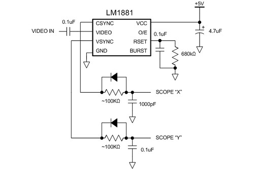
The LM1881 separates the sync signals from the NTSC composite video coming from the camera. It outputs a vertical sync signal (active low) that asserts during the vertical retrace period and a composite sync signal (also active low) that asserts during the horizontal retrace period and also during the vertical retrace period (but with a set of serration and equalization pulses).
To connect these to my oscilloscope, I have to use the XY mode on the scope and convert the sync signals into deflection signals. This is done using analog ramp generators. The simplest way is to use an RC circuit to generate a rather nonlinear ramp. When the sync signal goes high, it charges the capacitor through the resistor. When the sync signal goes low, the diode allows the capacitor to discharge immediately. This generates the sawtooth waveform. Adjust the R value so you get the most complete ramp (goes most of the way up to 5V).
The video signal is fed directly into the Z-axis signal at the back of the scope. Because the Z-axis signal has the opposite polarity from regular video (it is a blanking signal, where a positive voltage will turn the beam off), I had to build a really basic video buffer to invert the signal. This is a nice exercise in transistor biasing using four external resistors. Don’t ask me for the schematic–you should try to build it yourself. Even if you don’t get it working properly right away, you’ll discover all sorts of interesting analog video effects!
Giorgos Lazaridis :
Date: March 30, 2011 @ 1:01 pm
Mate, that is awesome! I had this in mind to do it myself, but you did it and it looks so cool! my congratulations! I will feature it in my site today!
Jeri Ellsworth :
Date: March 30, 2011 @ 5:28 pm
Nice and simple!
Gert :
Date: April 2, 2011 @ 2:27 am
Does it work with PAL?
eric :
Date: April 2, 2011 @ 7:06 pm
Yes, you’ll need to adjust the resistor values slightly but it will work just fine.
Mark Thoren :
Date: April 7, 2011 @ 11:46 pm
Eric, that’s awesome. I understand it used to be a common project, to turn a scope into a TV, when scopes were more common (and cheaper) than TVs. I could be wrong – could be urban legend. Anyway, I have a schematic in my archives of a project called the “Tele-Scope” that turns a television into a scope. It’s a sampling scope using an ADC to fill a block of RAM – probably way more complicated than it needs to be. I always thought it would be cool to have a scope-TV and a TV-scope, and you pulled off the first one with one chip!!!
Frank :
Date: April 23, 2011 @ 2:28 pm
Hey, I have that same scope! Bout it off ebay about 6 years ago, still works great!
Frank :
Date: April 23, 2011 @ 2:30 pm
Can you please send me the complete schematic? I don’t have enough experience to build this, and it is very cool!
MattT :
Date: June 22, 2011 @ 11:15 am
Hi Eric – love the project. I’m trying to emulate it at home. Had a couple of questions;
– In your description you send one composite feed through the circuit then to channels 1 and 2 of the scope (in xy mode) AND have the untouched composite signal to the Z input. Did you distro-amp the composite signal or just jump off the one composite signal? Does it need a power boost to work?
– I was also looking at this (http://www.electronixandmore.com/project/14.html) and while he uses the lm1881 like you, he’s also got 555s dealing with timing stuff to make sure the signals sync (if I’m reading this correctly). Did you not have this issue? Is that what the capacitors are doing?
I’m not having any luck with this (my background is not in electronics) and would love to find out why! Thanks so much for posting and INSPIRING us with your wonderful work!! Cheers!
eric :
Date: June 24, 2011 @ 6:15 pm
Matt, the capacitor/diode circuit generates the sweep signals (deflection) from the sync signals (pulses). First you should try to get that circuit working before you run the video into the scope. Check first the X for a sawtooth waveform, then the Y. Then put the scope into XY mode. Once you can see a solid box on the screen you can then run the video into the Z input. You might need to amplify it, but give it a shot first.
The 555 timer circuit is a bit too complicated, and all those extra parts aren’t really necessary.
GCL :
Date: May 3, 2012 @ 4:19 pm
Two things:
One what are you using to create the composite video that the LM1881 is translating into video levels?
Two are you aware that your extremely interesting idea has been shown on Hack A Day twice? Once here:
http://hackaday.com/2011/03/30/oscilloscope-thinks-its-a-video-monitor/ and then here:
http://hackaday.com/2012/05/03/watch-a-shop-tour-through-the-screen-of-an-oscilloscope/
I recall examining an excellent circuit using a pair of DAC parts and assorted discrete linear parts and perhaps an Op Amp or two to sort it out, as described by Steven Ciarcia, but as of yet I can not find the issue of Byte where it was described.
eric :
Date: May 6, 2012 @ 12:04 am
To generate the video I used a Quasar VK-100. The first link is my video, the second link is actually someone else who did the same thing. It’s an old trick anyway–my grandfather remembers some fellow students in the 1950s who were watching TV on a scope.
You could probably use DACs, but that would be overkill… Op amps could be used to make rather nice linear ramp generators.
Henry James :
Date: September 11, 2012 @ 9:20 pm
Interesting stuff.
I was wondering, is there a way to do this with pre-silicon chip parts?