A friend passed on the following articles regarding a rather famous hack:
https://news.ycombinator.com/item?id=7869771
http://www.jamtronix.com/blog/2011/03/25/on-the-trail-of-a-real-programmer/
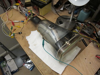
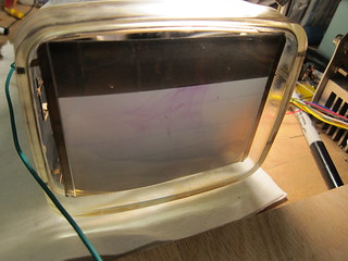
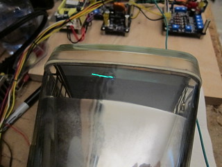
The LGP-30 was an early computer manufactured in 1956 and sold by the Royal McBee division of the Royal Typewriter Company. It had 113 vacuum tubes, 1450 diodes, a magnetic drum memory, and an oscilloscope screen with a template marking the register bits (instead of the more traditional panel with blinking lights). Mel wrote a lot of code for this machine, including a blackjack demo program, entirely in raw machine code, taking advantage of various quirks in the machine to keep the program very compact.
The Jamtronix blog has a link to a purported paper tape dump of Mel’s program.
Foolishly I decided to figure out the paper tape dump. I succeeded, and it looks like it’s in a format that a bootloader was supposed to understand, but not the bootloader documented in the LGP-30 manual. So first I ran the raw file into a popcount routine to see what the most common letters were. It was a subset of the alphabet, but had all the numbers except for the number ‘1’.
Wat?
Back then they did a few strange things. One of them was using the lowercase letter ‘L’ as the number 1. Right. Also, since the LGP-30 was hexadecimal, they used extra letters to represent numbers beyond 9, but instead of using a-f, they used fgjkqw.
Then the single quote ‘ is used as a record delimiter, and the letter ‘v’ at the beginning of the block of records identifies the track and sector where the data is to be loaded. Each block has 64 words, 8 per line (which fits perfectly in a single track on the magnetic drum memory). To save space, they omit leading zeros, so incoming characters of 4 bits each are shifted left 4 at a time. At the end of the block is a stray word whose purpose I cannot figure out. I suspect it’s a parity or checksum, but it doesn’t match a simple checksum of all the data.
This machine’s architecture is a clever nightmare. Self modifying code was encouraged and was the standard way to accomplish common tasks. For example, to branch to a subroutine, you do this:
1000: r 3050     <- Set up return address by writing PC+2 to the destination address of the instruction at 3050.

1001: u 3000     <- Unconditional branch to address 3000.

1002: ...        <- Magically we pop up back here!

...

3050  u 0000     <- Looks like a unconditional branch to location 0 right? No, it's just a placeholder address. Yay, we can do without a link register!
And Mel coded this up in machine code. Probably because the “assembly” mnemonics are not particularly helpful, he must have quickly memorized the opcodes themselves. And why did he use instructions as data? The machine doesn’t decode the upper 12 bits of a word, so if you didn’t use it, it was just wasted. Basically the architecture of the machine naturally led Mel down this slippery slope.
So you might think that Librascope/Royal McBee, based on customer feedback for this machine, must have simplified the design for a later machine, the RPC-4000. And you would be wrong–it’s even worse…
Anyway, here’s my disassembled version: blackjack.txt. The track number is listed first, once for every block. In each block, every line has the sector number first, followed by the instruction mnemonic, following by the track and sector numbers of the instruction’s target. After that are the raw bits. The first two instructions are clear instructions followed by an unconditional branch. This goes to track 49 sector 34. You can follow the instruction flow from there.
As for me, I’m going to stop now before I accidentally learn how to program the LGP-30.