3D Vector Graphics
February 19, 2014 Projects 2 CommentsIt’s back! This is a new vector CRT driver setup. The 3D cube is generated by an Arduino driving an 8-bit DAC.

It’s back! This is a new vector CRT driver setup. The 3D cube is generated by an Arduino driving an 8-bit DAC.
My friends at Evil Mad Scientist have a new kit for sale. It’s a 555 timer circuit that you can build yourself using discrete transistors. You can wire it into all sorts of 555 timer circuits and then probe individual nodes to see how the chip actually works.The circuit board that you get with the kit has silkscreen labels that mark the functional blocks of the circuit, and silkscreened component designators that match up with the “official” Signetics schematic.
The circuit is full of interesting analog electronic design elements. You’ll be able to play with differential pairs, current mirrors, Darlington stages, diode-connected transistors, and more.
It’s a great kit if you want to learn more about how integrated circuits work, or if you’re a fan of the indefatigable 555 timer and want to have a neat conversation piece, or even if you’re just a beginning electronics hobbyist and you want to practice your electronics assembly and soldering skills.
It’s been quite some time since I last posted about this. The project has been on the back burner for some time now since I’ve just been so busy with other things. It’s actually pretty far along the process but the cost of the parts is just too high, and the kit has quite a few parts.
I’ve been revisiting the design again to see if I can make it easier to build and less costly.
A question: Would you consider a version without a DAC? Instead of having an 8-bit digital interface (Arduino compatible), it would have analog X and Y inputs and a video/blanking input.
If the site’s been very slow for you lately, it’s because someone used a PHP injection attack to add some potentially malicious Javascript to the top of the page. It should be fixed now. Thanks to Olli for the tip.
Several months ago at the electronics flea market I picked up a neat bit of brass. I did some internet research and it’s actually part of a 19th century scientific demonstration instrument, most likely a prism. I found a very similar example at Fleaglass. Theirs sold for quite a bit of money, but I got mine for $5, which is probably about the value of the brass in it.
So I turned it into a table lamp.
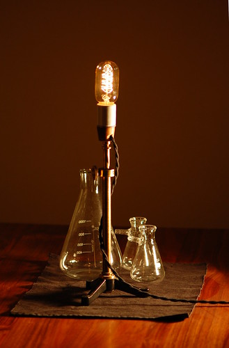
In the photo I’ve installed one of the many vintage-style reproduction light bulbs that are starting to appear. They don’t really look like a nice carbon filament bulb but I can use this every day and not worry about it burning out.
Now all I need to complete it is to put a shade on it. Ideas?
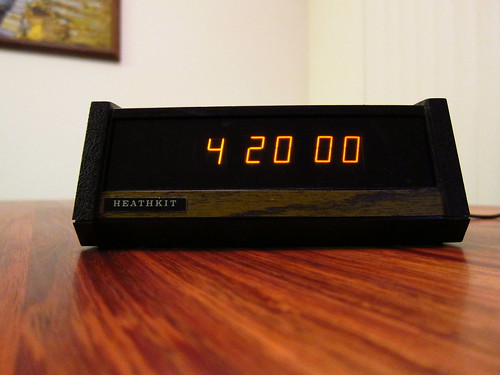
Remember my Panaplex clock project? Here’s a present: the design details!
Wow, it’s been a few months since my last post. Sorry for the blog silence. I got very busy with a new job and just haven’t had the time to work on projects at all, let alone blog!
So here’s a quick one–it’s a Heathkit GC-1005 digital clock that uses Panaplex displays (Neon filled). I picked it up at the electronics flea market and it looked like someone had been trying to get it working before me, and they left a bit of a mess. I had to clean up the wiring job and check the electrolytics to make sure they were still good (they were).
The reason it wasn’t working right is that some of the component leads on the bottom of the PC board had poked through a paper insulator and shorted out against the switch contacts on the bottom of the case. All I had to do was trim the component leads and fix the insulator.
My new CRT driver board is coming along rather nicely. Tonight I tested it out with a 5″ CRT. It uses a P7 radar phosphor so it looks bluish white with a sickly yellow persistence.
The pattern is a Lissajous figure (LISS-uh-joo). Take two waveform generators and connect one to the X input and the other to the Y input, and you get all sorts of interesting patterns. Since the CRT driver board is not available as a kit (not yet, anyway!) you can duplicate this with an oscilloscope and two function generators.
There’s some interesting math behind Lissajous figures, but I’m more interested in building 3KV power supplies.
At Maker Faire, a lot of people asked me if I had a kit available for any of my CRT clocks. Based on the amount of interest, I’ve decided to put together a kit that will make it easy for people to drive cathode ray tubes using simple digital or low voltage analog control signals. The kit will include a PC board and all the components as well as detailed assembly instructions. For people that opt to use the digital interface, the kit will also include source code libraries making it easy to generate simple vector graphics.
The kit will use surface mount components, but none smaller than 0805. The ICs will be SOIC or SOTs, with the exception of the DAC, which is TSSOP.
Because this would be the very first surface mount kit many people attempt, I’m trying to figure out an approach for the assembly instructions that will make it easy to succeed. Some ideas I’ve had so far are:
Hobbyists seem to have an aversion for surface mount components. With a little practice, I’ve found that it’s faster and easier to use surface mount components. Think about all the time you could save by not having to bend and clip resistor leads. You can solder most of the components without having to flip the board over.
If you have any ideas, please feel free to comment. This is all still in the early stages so there is plenty of room to change things and try new approaches.
The Maker Faire is a neat DIY convention that happens every year. I’m bringing some of my projects to the Maker Faire Bay Area; just look for Tube Time. Come and say hello!