
Dekatron Kitchen Timer
April 5, 2009 10:43 pm ProjectsRecently I completed the construction of a Dekatron-based kitchen timer. A Dekatron is an electronic counting device used in the middle of the 20th century for counting pulses or dividing input pulses. You can find a very good introduction to the devices at Mike’s Electric Stuff. My timer is certainly not the first. This gentleman has created a rather military-looking kitchen timer that uses three Dekatrons.
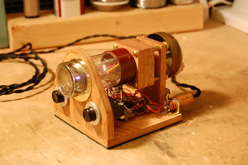
Dekatrons are relatively difficult to find, so I decided to use a single Dekatron in my timer. Actually this project is an old one that I revisited. The original project was just going to be a spinner, but I had trouble with the driving circuit (it never worked reliably). For the 2008 Maker Fair I dusted it off and tried to power it up–with 12V instead of 5V. The power supply and microcontroller did not appreciate it and the whole thing stopped working. The second time around I decided to turn it into something useful. Here it is.
The driving circuit in the Dekatron kitchen timer is based on a circuit drawn up by Mike Moorrees. You can find the circuit at the NEONIXIE-L mailing list files section. There’s a good excuse for you to join. If you’re interested at all in antique display devices (not just Nixie tubes) you need to join.
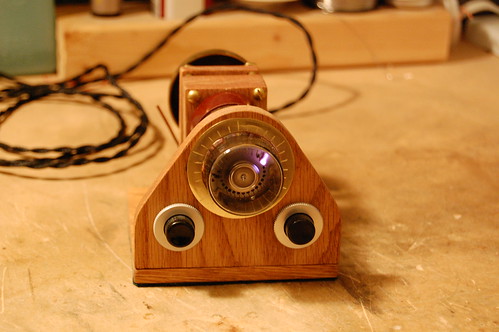
There are twenty minutes remaining on the timer. You can read the time using the scribed lines on the brass ring around the Dekatron. The ionized gas in the tube glows purple because of the high argon content.
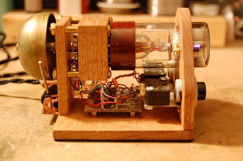
In this side view, you can clearly see the high voltage power supply. It has a copper-wound ferrite toroid. The power supply converts 5V up to 450V by a MAX845 that pulses the transformer at 535KHz, and the 150V output of the transformer gets stepped up to 450V through a 3-stage voltage multiplier.
Time is kept and the clock is controlled by a PIC16F84. The brass bell at the end rings once the timer expires. After ringing the bell, the PIC turns off the high voltage supply and enters sleep mode. Pressing a button wakes up the microcontroller and begins a timing cycle.
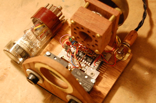
You can see the socket more clearly when the Dekatron is removed. My homebrew drill press for my Dremel tool helped tremendously to drill accurately-placed holes for the pins.
On the right side the power connector provides 5V to the timer from an old cellphone charge adapter. Don’t throw away these adapters! The small ones often contain a very simple off-line isolated power supply that can be modified to produce other output voltages. You can recycle them for projects quite easily. Perhaps I will write an article on this.
The 5-pin connector on the board is used to program the PIC. The PIC16F84 is old enough that it does not support in-circuit debugging. It was Microchip’s very first product on their flash process which has made them so much money over the intervening years.
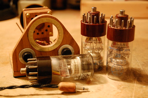
Here is the extent of my Dekatron collection. They are all type GS10D, which is a decimal selector tube with two sets of guide electrodes. The Dekatron in the front of the timer does not work. Can you see why?
Alessandro :
Date: April 6, 2009 @ 12:30 am
Bellissimo !
Everything in the project is nice but I expecially love the wooden 3.5mm plug. Excellent woodworking :
at first I though you did it with CNC but then I realized you did it with a Dremel ? Wow !
Mhhh….I have two spare Nixies !….
Kitchen timer ….Mhhh.
Ciao
Alessandro
Dekatron kitchen timer - Hack a Day :
Date: April 6, 2009 @ 10:37 am
[…] put together this beautiful kitchen timer using a dekatron. We see all kinds of tube projects, but dekatron projects are fairly rare. The […]
philpem :
Date: April 6, 2009 @ 12:12 pm
Just saw this on Hack A Day. It looks really neat, and the wooden 3.5mm plug is the icing on the cake.
Two questions though:
– What did you use for the valve pins inside the wooden socket?
– What sort of cable did you use for the 5V connector (as shown in the last photo)? I’ve never seen anything quite like it.
The only thing I’d have done is add a thin piece of wood (with a hole drilled to suit the valve base) to the front of the Dekatron socket, just to stop any small conductive objects shorting against the tube pins. Probably more effort than it’s worth, though.
As for the reason for the death of the GS10D in the last photo? I’d go with an air leak — the silver air-absorbing “getter” has turned white, which suggests the sealing pip has failed, and let the neon/argon fill escape.
eric :
Date: April 6, 2009 @ 4:32 pm
The valve pins are made out of 1/8″ diameter brass tubing with a slot cut across. I glued them in with JB Weld.
The wire is from Sundial Wire (http://www.sundialwire.com/).
There are plenty of places that could be shorted by loose metallic objects. I went for the “open” look, but I may need to come up with a plastic cover. Any ideas?
The GS10D in the last photo may have been dropped or subjected to excess vibration. It could also have been slightly leaky from the factory.
clint :
Date: April 6, 2009 @ 6:39 pm
Very nice project! I like the wooden socket and the bell too.
For a cover, may I suggest trying to mold the circuitry into some transparent potting material.
Good job,
Clint
Iain Sharp :
Date: April 7, 2009 @ 2:32 am
Lovely work – all your projects are great. I wish I had your woodworking skills.
I have just completed my first project involving interfacing Nixie tubes to an AVR microcontroller, so I am feeling pretty pleased with myself.
Jadrian :
Date: April 7, 2009 @ 4:04 pm
Hi Eric, beautiful work! For the cover, I’d suggest making the wooden back piece (to which the bell is attached) have the same shape as the front piece (where the buttons and display are) and then using a router to make a groove just inside the edges of these two pieces. You could then make a single piece of clear acrylic fit into the grooves and cover all the internals. The result would look like a house with a single, continuous, clear piece forming the side walls and roof, while the front and back walls extend just outside this piece.
Seems to me this wouldn’t screw up the aesthetic you’ve already got going too much. It would be sort of a chore but this is already such a polished piece of equipment it’s worth spending some effort on the rest of the enclosure.
spuffler :
Date: May 7, 2009 @ 9:41 pm
Wow. The proposed cover for this device is crying for chocolate color. If I thought it could be hobbied, I’d think dark brown Phenolic like was used for 5 tube Zenith AM radio housings of the late 1950’s. Otherwise, maybe a brown crinkle paint over a formed sheetmetal cover? I’m loving this stuff as well as steampunk.
blo :
Date: January 28, 2010 @ 12:49 pm
hi there.
this is an amazing piece of work!
any chance to get the pcb, so i could build my own?
thanks
gob :
Date: December 30, 2012 @ 5:58 pm
Have you done anything else to this project since this post? I’d love to do something along these lines. Would you consider sharing the board design? Apologies if you already have and I haven’t looked hard enough.