
1948 Philco 48-225 Table Radio
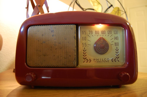
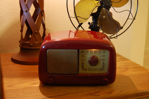
November 14, 2009 4:31 pm RestorationRecently I completed restoring a Philco 48-225 AM tube radio. This radio was produced by Philco in 1948, and it was one of the first radio models to have a plastic (polystyrene) case instead of a bakelite case.
When I received the radio, the case was pretty scratched and banged up, and there was a big crack on the left side. Inside was a lot of dust and bits of dried leaves. Most of the tubes were missing, and the ones that came with it were the wrong type.
The case cleaned up nicely after a lot of wet sanding with fine-grit sandpaper and polishing with Novus 1, 2, and 3. The gold paint on the speaker grill was flaking off, but I decided to leave it alone. I saw a photo of the same model radio on eBay and someone had ruined the grill by trying to polish it–the gold paint is a very thin layer and it came off in patches.
Using superglue I fixed the crack and sanded it so that it’s barely visible. I hear you can also use a solvent-type glue, but I didn’t have any. The superglue repair is probably fragile so I will have to be gentle.
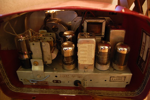
Turning the radio around, you can see the “All-American Five” tube complement. They are the 7A8 converter, the 14A7 IF amplifier, the 14B6 2nd detector/1st audio AVC, the 50L6GT audio output amplifier, and the 35Z5GT rectifier. All the tubes except for the 35Z5GT are of the Loctal variety. Unfortunately the back cover of the radio is missing.
Here is the underside of the chassis before I restored it. You can see how the paper capacitors are coming apart due to age. These radios were designed to be very low cost and were not supposed to last a very long time. The sectional electrolytic capacitor (the long pale tube on the upper right) in particular did not work at all because the electrolyte had seeped out completely.
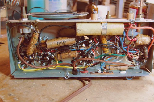
I ended up replacing most of the capacitors. For this restoration I pushed the guts out of each capacitor and slipped the new capacitor inside the old one, sealing the ends with wax. This keeps the underside looking authentic.
Notice that there is no power transformer inside this radio. This radio operates directly off the AC line. The filaments for all 5 tubes are wired in series and the voltage ratings add up to the line voltage. The chassis itself is not grounded and it is actually part of the antenna circuit. There is a 150K resistor connecting it to one side of the AC line. The plug is not polarized so it’s quite easy to shock yourself on any exposed metal. It’s not a good idea to plug it straight into a wall socket because of this. If you try to add a 3 conductor line cord with the ground prong connected to the chassis, this will short out the radio’s antenna and the radio won’t work.
The solution is to use an isolation transformer. I have one connected to a Variac that I use to adjust the line voltage. When I first powered up the radio, I ramped the voltage up slowly to make sure there were no problems along the way. I also measured the line voltage and set it to 115V instead of 120V. AC line voltage was a little lower back in 1948. The difference doesn’t sound like much but running at the higher voltage would apply 6.6V to a tube filament rated at 6.3V. This is enough to reduce the life of the tube.
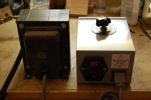
With the radio plugged in to the isolation transformer, the radio “floats” relative to the AC line, and it’s safer to touch exposed metal. It’s still a high voltage circuit so the one-hand rule applies. When the radio is isolated like this, it’s also safe to connect it to pieces of test equipment, such as an oscilloscope. The oscilloscope probe ground actually connects to the ground pin on the oscilloscope’s line cord, so if I had tried to test the radio when it was plugged straight in, I could have caused a short circuit that would have melted my scope probe.
It sounds pretty good now and it adds a vintage touch to the living room decor.
Àlber :
Date: March 31, 2011 @ 1:45 pm
Hi! You have a nice blog here 🙂
I’ve got a question. What’s the ‘one-hand rule’ you state in “It’s still a high voltage circuit so the one-hand rule applies.”?
Thanks!
eric :
Date: April 1, 2011 @ 2:54 pm
When you work on a high voltage circuit, it’s a good idea to keep one hand behind your back or in your pocket so you don’t try to grab parts of the (live) circuit with both hands, which could allow current to flow through your heart.
Jon Hendry :
Date: May 6, 2019 @ 10:36 am
If you still have this radio you could try gilding the grille. There are a variety of gilding materials you could use, in a variety of colors. Gold, silver, faux version, and also various mixes of color flakes providing a variegated effect.
Basically you paint it with sizing, which is just a clear paint that stays tacky for 24 hours or so. Then you lay the foil on the sticky sized surface and burnish it with a smooth tool. I think the traditional tool is a piece of agate with a handle, but the bottom of a plastic spoon would probably work.