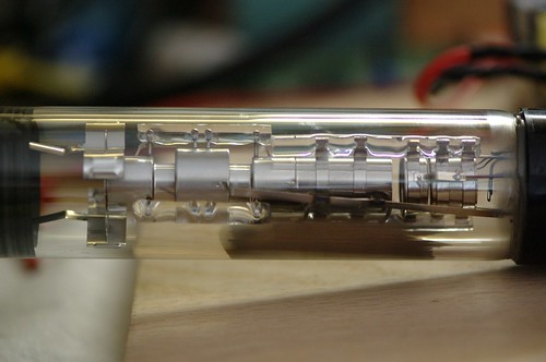
Electrostatic CRT Driver Design
May 31, 2014 Projects 62 CommentsUpdate 23-December-2014: Richard at LabGuy’s World has wiring diagrams for the RCA 913 and the 3JP7, and other neat stuff.
Update 23-June-2014: Please see the CRT Board BOM Updates page for important changes.
Update 3-June-2014: Added OSH Park links so you can order PCBs easily and quickly!
Well, it’s here! I’ve put together an open source release package for my CRT driver design. See all the glorious details at the GitHub project. It contains the fab data (Gerbers, NC drills, etc) as well as the CSV-formatted bills of materials for three boards. All the parts are available at Mouser Electronics (and the Mouser numbers are listed in the BOM). It’s the same set of boards that I used for my Asteroids and Flappy Bird arcade machines at Maker Faire.
The design can drive most 2″, 3″, and some 5″ electrostatically-deflected cathode ray tubes, such as the popular 3BP1 or the precision 3RP1A. It can be modified to drive some of the oddball 2″ and 3″ CRTs that have a shared heater and cathode connection.
The three boards are:
- 1KV power supply (Order from OSH Park)
- Electrostatic CRT deflection and video amplifier (Order from OSH Park)
- Video amplifier bias supply (Order from OSH Park)
The 1KV power supply takes +12VDC and uses a Royer oscillator with an off-the-shelf CCFL transformer to create filtered 800-1200VDC. The voltage is tuned by adjusting R1. Use a plastic-handled pot tweaker tool please! The supply can easily source several milliamps, which at 1KV could stop your heart. This is a serious power supply, so please be safe if you decide to build it. Keep one hand in your pocket while using it. Turn the supply off before poking at it, waiting at least a second or two after switching off the DC supply to allow the sense resistor divider to bleed off the output voltage. Don’t work alone.
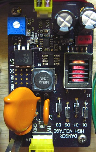
The design is inspired by CCFL circuits designed by Jim Williams–see the very long and wonderful AN65, especially Jim’s hand-drawn notes at the end. While Jim used a switching regulator to drive the Royer circuit, I used a simpler linear FET approach which works well but generates more heat. You will need to screw a metal heat sink to the plated through-hole located above Q1. Use a mica washer and a nylon screw if you want electrical isolation since this node is NOT ground.
If you want to put this in an enclosure, keep a clearance gap of 1cm or more between HV connections and low voltage nodes or a metal chassis. The power supply produces stray magnetic fields that will cause the electron beam in a CRT to deflect in ways you don’t want, so you should keep it far away from the CRT and use a CRT shield made out of high magnetic permeability material, like mu-metal or soft steel.
You can also add a voltage multiplier circuit, tapping in to diode D1, to generate post deflection acceleration (PDA) voltages. A 2-stage multiplier (as shown on the schematic) can generate 3KV which is fine for 3″ and 5″ tubes that require it.
At the heart of the design is the electrostatic CRT deflection and video amplifier circuit, which takes 0-3.3V analog signals for X and Y deflection as well as the video input, and outputs high voltage drive signals to the CRT.
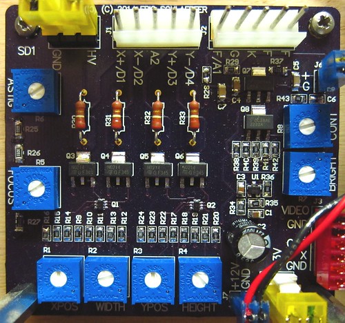
There are two deflection amplifiers, one for X and one for Y. The core of the differential amplifier is a matched dual NPN transistor with a bias circuit for setting the gain and offset (width/height and position potentiometers). A cascode stage made out of two high-voltage NPN transistors increases the bandwidth slightly and level shifts the signal up to about 1KV. There are two 220K resistors that form the load for the circuit. Don’t substitute these with plain carbon composition resistors–these parts have to be rated for high voltage use. Bandwidth of the amplifiers is about 10-15KHz, so you could drive ramp signals in to X and Y and generate an NTSC sweep if you wanted.
The video amplifier is a pretty simple class A design with a cascode stage to increase the speed. Bandwidth is about 6MHz, so the circuit can easily handle NTSC video. A simple-minded approach for driving a CRT electron gun is to ground the cathode and drive the grid negative, but the circuit design ends up being tricky. An easier way is to drive the grid to ground (or in my case, to an adjustable brightness voltage from a potentiometer) and connect the cathode to the amplifier output. The end result is the same, although there is a slight impact on the focus electrode. The video amplifier uses a +60V bias voltage which needs to be rather stiff since the drive current is fairly high (required to get 6MHz bandwidth).
A focus potentiometer produces a bias voltage for the focus grid in the CRT. It’s adjustable over a fairly wide range covering most 2″, 3″ and some 5″ CRTs, but if you’ve found some oddball CRT, you could always change some of the other resistor values.
The astigmatism potentiometer changes the final accelerator voltage relative to the average deflection plate voltages. Adjust this potentiometer if the spot on the screen looks oval instead of round.
There is a connector for a 6.3VAC filament supply. You don’t have to use an AC voltage, but be aware that pin 1 is tied to ground. You might want to measure the actual output voltage of the filament transformer (under load of course). I’ve found that most of them tend to run high (7V is not uncommon). Adding a series resistor can help prolong the life of the CRT.
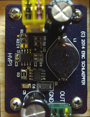
Finally, a video amplifier bias supply generates +60V for the video amplifier. As an “easter egg”, you could modify this circuit to operate as a Nixie tube power supply by changing the value of R1. You’ll also need to increase the voltage rating on C5.
If you’ve already looked at the GitHub project, you might have noticed that there are no design files. I use Altium Designer for my schematics and PCB layouts. It’s a fantastic tool, but Altium’s decided that hobbyists are not a target market so this is a very expensive product that not many hobbyists own, so I don’t think there’s much point to posting design files. Maybe if Altium releases a noncommercial free license, but I doubt that will happen. Altium recently raised their prices by $2K so the direction they are going in is pretty clear.
I’ll be posting updates with additional information, such as a CRT compatibility table, pin connection tables, and so forth.

