
Miniature Coin Cell Nixie Tube Power Supply
November 2, 2014 9:32 pm ProjectsUpdate 11/3/2014: Fixed the coil connections on the schematic, along with the inductance. Also, check out this post to see how the circuit works.
This project has been a long time in progress. It started years ago at a Maker Faire where I built a Nixie tube pendant powered by a lithium coin cell battery. Since then, I’ve decided to make a PC board and put together some instructions on how to build such a power supply yourself. These little supplies are great for steampunk jewelry or possibly single-digit Nixie tube clocks (they’re not quite strong enough to drive multiple tubes). The battery life should be around 3 hours or so for a CR2032 lithium coin cell.

The schematic is below–click for a larger view. The bill of materials is located here, including Mouser Electronics part numbers. If you decide to order, get at least 5 of each part just in case you lose or burn up some of them. Note: Mouser seems to be out of stock for the T1 inductor, but Digikey has it here.
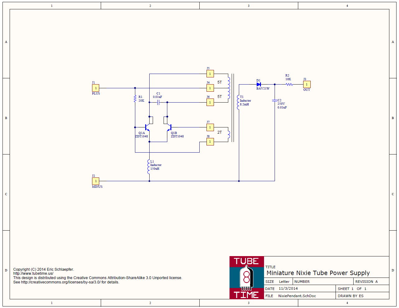
Q1 is a single device; it actually contains two transistors which is why it looks like that on the schematic.
To make it easier to build, I’ve put up a convenient OSH Park project page link so you can order boards. When I ordered from them, it cost $2.80 for a set of three boards (with free USPS shipping). Not a bad deal at all!
When you have boards and components, there’s a specific order of assembly that makes things a bit easier. See this YouTube video:
Basically you need to assemble the components in the following order:
- Solder C1.
- Solder Q1. Be sure you line up the beveled edge with the extra-wide silkscreen. If you put it in backwards the power supply will not work.
- Flip the board over.
- Solder D1, then R2, and then C2. C2 is 0.01uF, similar to C1, but it has a 250V rating. It is very important not to mix these up.
- Solder R1, and then T1 (the big coil, not marked on the silkscreen).
- Take a piece of 32 gauge magnet wire that is 13 inches long and tin about 1/8 of an inch at one end. I use a soldering iron to burn off the varnish. Solder it into the upper left through hole that is below the coil.
- Wrap 5 turns clockwise around the coil T1. Thread the end of the wire into the middle through hole below the coil.
- Turn the wire around and thread it back through the same hole, pulling it tight to form a tiny loop. Solder the loop to the through hole.
- Take the wire and wrap another 5 turns clockwise around the coil. Thread the end through the top right through hole below the coil, and solder it in place. Trim off any excess.
- Get another piece of 32 gauge magnet wire that is 5 inches long, and tin about 1/8 of an inch at one end. Solder it into the lower left hole that is below the coil.
- Wrap 2 turns clockwise around the coil T1. Thread the end of the wire through the lower right through hole that is below the coil. Solder it, and then trim off any excess
- Solder the inductor L1. The reason it needs to be soldered last is that it makes it hard to wind wire around the coil T1.
- Solder connecting leads to the +, -, and OUT terminals.
To use it, connect a coin cell’s negative terminal to “-,” the coin cell positive to “+,” and “OUT” to the anode of a Nixie tube. The Nixie tube cathode goes to the coin cell negative terminal. Don’t touch the “OUT” terminal–you could get a shock. In fact, if you build the power supply into jewelry or something people will be touching, insulate all the connections.
Have fun!
Richard :
Date: November 3, 2014 @ 4:54 pm
Are the J4 / J5 pins swapped on the schematic? Shouldn’t B+ go to the center tap?
eric :
Date: November 3, 2014 @ 6:16 pm
It’s fixed, thanks!
Labguy :
Date: November 4, 2014 @ 6:17 pm
You’re welcome!
Adam :
Date: August 21, 2015 @ 7:33 am
I would ask you if this power supply can charged two nixie tube like: Burroughs B-5870 ???
eric :
Date: August 21, 2015 @ 5:30 pm
Adam–it would be hard for it to drive two nixies at the same time.
Oleksiy :
Date: September 30, 2015 @ 6:53 am
Hello Eric,
I cannot order the boards with your link, as it asks to sign in first. Is it possible to do?
Cheers,
Oleksiy.
Oleksiy :
Date: September 30, 2015 @ 7:04 am
I’ve got it and ordered the PCBs. Thanks for your creativity 🙂
Damian1384 :
Date: January 9, 2016 @ 3:13 am
Like Oleksiy, I would also like to order your board and need to sign in first. I recently had a college class about making inductors by hand, the teacher used to be part of a design team that made radios for the military and wanted to teach a hands on project on the subject. I was going to try winding an inductor by hand using left over parts to make a royer Oscillator. I wanted to make a Nixie tube driver since I saw a version of this project using a disposable camera to drive the tube a few years ago. Your solution is perfect and I love it.
Damian1384 :
Date: January 9, 2016 @ 3:36 pm
Figured it out, ordering some now.
Alfred :
Date: April 13, 2016 @ 10:25 pm
Does this work with the Russian in 12 Nixie tubes?
eric :
Date: April 26, 2016 @ 10:14 pm
I have not tried it with in-12s, but it should work.
Nick :
Date: April 29, 2016 @ 2:13 am
Hi, thanks for this, I plan on making a nixie watch with this power supply and an arduino. I’m unsure though, can I power this with a 3.7v lipo (4.2v when fully charged) instead of the coin cell?
eric :
Date: May 11, 2016 @ 5:20 pm
Nick, you can. It will be able to source a bit more current which is nice.
Nick :
Date: May 26, 2016 @ 2:30 pm
Great stuff, thanks for the tutorial and help 🙂
Dennis :
Date: August 18, 2016 @ 1:52 pm
Picasa is gone, so the schematic isn’t available. Can you update the link?
eric :
Date: August 30, 2016 @ 9:35 pm
Fixed.
Michel :
Date: February 22, 2017 @ 11:20 am
I am planning to use your circuit for a watch and therefore I need to turn off the circuit most of the time in order to save the battery. How would you suggest implementating an enable circuit with your design?
eric :
Date: February 25, 2017 @ 1:09 am
It depends how you want to control it. A p-channel MOSFET in series with the battery supply is probably the easiest. Make sure it has a very low threshold voltage so you can turn it on even when the battery is low.
Michel :
Date: March 3, 2017 @ 5:04 pm
Thanks!
Phil :
Date: March 29, 2017 @ 3:52 am
Thank you for all your work on this project. I scoured the interwebs looking for something like this. So again, Thanks. I am a novice when it comes to this sort of thing so forgive my basic questions in advance. I want to build a single nixie tube thumb drive for a friend and fellow systems engineer. I’d like to use the IN-19A tubes. Specs show 170v to fire and 150v to sustain. I’d like to bring power from the + – 5v leads (2 leads as opposed to your 3) on the thumb drive. Would your application, as designed, first power the IN-19A and secondly, would anything need to change in your schematic to do this? Besides eliminating the battery. Basically, I’d like the nixie to cycle through the available displays as the drive is ‘working’. Again, I apologize for all the questions and in the meantime I will keep digging but I am just coming up empty for a DIY on this exact application. By the way, your assembly video is very well done. Cheers.
Sergey :
Date: April 5, 2017 @ 8:28 pm
Hello, I have z5990M, but this scheme does not work. Output voltage 170V? but tube not burn. If there are ideas I will be grateful.
Paul :
Date: May 18, 2017 @ 7:17 pm
Hi,
I was wondering if it was possible to simulate this in spice, so as to play around with some of the values and see what happens.
Going to build this anyway.
BTW. What is the source of the limitation on output current?
Thanks.
Per Jensen :
Date: November 4, 2017 @ 1:40 pm
Hi! – I’ve built three of these devices (one on trototype PCB and two on OSHPark-PCB’s) and i’m unsure about the component values as the schematic still refers to one with the connections swapped on the transformer.
I ordered the components shown on the DigiKey-list (that includes the 8.22uH inductor, and not 10uH as shown in the schematic. I get an open-circuit voltage of about 210V and it drops to about 120V with a load on (ZM1020 or similar Nixie) – It can barely light up the tube. Other nixies and neon bulbs tested as well. Any tips for achieving more output power when loaded down? Should i add more turns on the secondary of T1 to reach the 10uH? Thank you for coming up with this cool little project.
eric :
Date: November 14, 2017 @ 11:53 pm
You could try adding a couple more turns on the primary (5T to 7T, for example). The feedback winding should be OK the way it is.
kim :
Date: January 21, 2018 @ 3:14 pm
It’s a really good job.
I want to apply it.
I would like to use a single transistor instead of zdt1048.
Can you recommend a single transistor?
eric :
Date: January 21, 2018 @ 7:57 pm
Start with a 2N2222. It’ll take some experimentation.
kim :
Date: January 21, 2018 @ 4:26 pm
Image link>>>
https://drive.google.com/file/d/1-itJjAipYmjNRe5xfb6PlxA7WJvTN6T2/view?usp=sharing
kim :
Date: January 22, 2018 @ 3:48 am
Thank you.
I have 2n2222!
Danny :
Date: April 29, 2018 @ 9:14 pm
I tried changing it from 5 turns to 7 turns in various combinations, but it had no effect on the output. It is still unable to fully light the tubes. Any other ways of increasing output?
eric :
Date: April 30, 2018 @ 10:10 pm
Try to find an inductor with a higher value. This usually means it has more turns on the “secondary” thus increasing the output voltage. As an alternative you could put a diode-capacitor voltage doubler on the output instead of the simple rectifier.
Danny :
Date: May 1, 2018 @ 3:43 am
Ah, yes, as it turns out I bought 8.2mH inductors, instead of the 10mH inductors. Gonna go buy the correct gones
Chris Fawcette :
Date: May 1, 2018 @ 11:31 am
Would you sell one pre made with a tube
eric :
Date: May 22, 2018 @ 10:27 pm
No, but I’m hoping that others will do so since the design is open source.
Adam :
Date: November 12, 2019 @ 12:40 pm
Hi Eric,
Could You add schematic once again? File not exist anymore.
Ryan Bareither :
Date: November 24, 2019 @ 5:21 am
When I type in the part number for L1, It comes up with four options. What one would I need? Type EF, EFD, or PF? They look pretty much the same except the ohms.