
Miniature Nixie Power Supply – How it Works
November 3, 2014 7:48 pm ProjectsFor more details and the video about the miniature Nixie power supply, see my original post.
First off, this circuit is not a Royer oscillator. As summarized by Jim Williams in his famous app note AN65, Royer developed a power converter using a transformer that saturates every cycle.
A coil saturates when the magnetic field (the B field) has reached the maximum that the magnetic core material can support: if the current (which is what creates the magnetizing H field) increases more, the magnetic field increases very little. The inductance, which is proportional to (B ÷ H), rapidly drops off, causing the current in the coil to increase at a much faster rate. Royer’s design detects this current spike and uses it to switch the transistors (2N74s, in his original paper) into their opposite state.
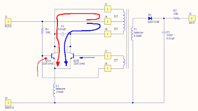
My circuit is a more common LC resonant converter. There are two transistors, Q1A and Q1B. Resistor R1 provides the bias current for the transistors and gets things started. Current (represented by the large red arrow) flows through the center tap of the coil T1 out to Q1A through its collector. The current in the upper half of coil creates a magnetic field, and the magnetic field induces a voltage in the feedback coil. This voltage reduces the base drive for Q1A and increases the base drive for Q1B (represented by the small blue arrow). When that happens, Q1A shuts off and Q1B turns on. The current in Q1B’s collector (represented by the large blue arrow) creates a magnetic field of the opposite polarity in the coil, and therefore causes the feedback winding voltage to reverse polarity (see the small red arrow), turning off Q1B and turning on Q1A. The cycle repeats as long as there is power.
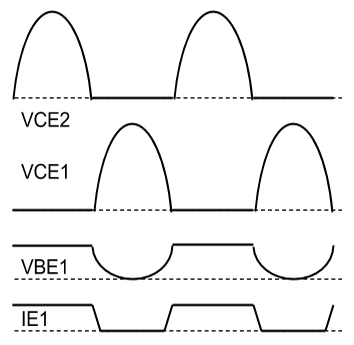
Above are some approximate waveforms. You can see that the transistors go back and forth, driving the coil first one way and then another. Capacitor C1 and inductor L1 help determine the resonant frequency of the circuit. If you measure the voltage across the entire coil, you’ll see a sine wave.
The output winding of the coil has a lot more turns than the input winding, and it increases the voltage (at the expense of the current) dramatically. This high voltage AC goes through the half wave rectifier formed by D1 and gets filtered to DC by C2. R3 limits the current into the Nixie tube.
You might be wondering why T1 is actually an inductor–an 8.2 millihenry one. It just makes the project easier to build. You only have to wind 12 turns on an off-the-shelf part instead of buying a hard-to-find transformer core and adding all the windings yourself.
If you feel so inclined, try adjusting the component values. Start with C1 and then maybe R1 or even L1. Try changing the number of turns on the coil.
Paul :
Date: May 28, 2017 @ 9:14 pm
Hi,
I have been trying to implement an LTSPICE simulation of this curcuit, with some success. One issue that I have found hard to resolve is getting the polarity of the windings right. Could you let me know what they should be? Also, the only things that affect the voltage in my simulation are the values of C1 and the number of windings – which doesn’t surpise me much. If I drop the value of R1 too far I get an HV chaotic mess of several KV.