A customer recently asked us some questions about the Three Fives discrete 555 timer kit. One in particular really got my attention.
What is the difference between the National Semiconductor LM555 and the Signetics NE555 timer ICs? Well, the Signetics part certainly came first and the National part was a second source, but the customer noted that The 555 Timer Applications Sourcebook, on page 5-31, states
…Table S-2 points out that the threshold overrides the trigger for the type LM555H (National), but the threshold is overridden by the trigger for the type NE555V (Signetics).
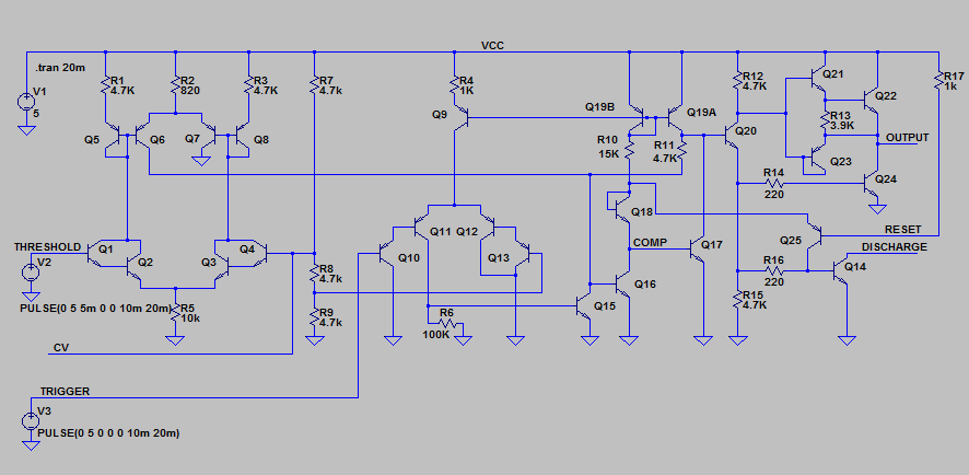
Let’s compare the two. First, here’s the NE555 schematic (click for larger versions).
And here’s the LM555 schematic. I’ve kept the component numbering consistent with the NE555 datasheet rather than National’s datasheet to make comparisons easy.
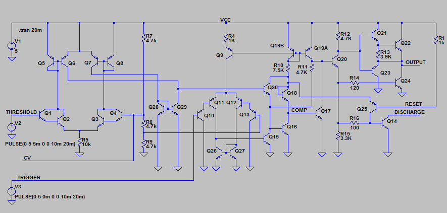
The LM555 makes three minor changes to the timer design:
- The trigger comparator now has a current mirror active load (Q26 and Q27) instead of resistor load R6.
- The threshold comparator gets a current mirror active load (Q28 and Q29) and an emitter follower buffer Q30.
- R10 is now 7.5K instead of 15K, but I suspect there is a typo. Imagine several generations of photocopies. The 1 starts to look like a 7, and a decimal point appears.
The most interesting changes are the first two. How do these changes reverse the priority of the two comparator inputs?
The original NE555 gives priority to the trigger signal because transistor Q15 can always overpower the current coming from Q19A and Q6.
For the LM555 in the normal case where the trigger signal is active, Q15 is on, Q16 is off, and Q17 is on hard since its base is pulled to VCC through Q18, R10, and the current mirror Q19.
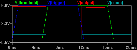
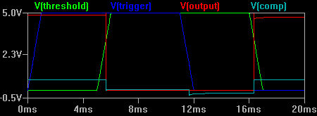
However, if both the trigger and threshold inputs are active, then both Q15 and Q30 are on. This leads to an interesting situation where the collector of Q18 is pulled to ground through Q15 and Q30. At that point, there’s nothing to provide current to the base of Q17, and any residual charge will probably drain away through the reverse leakage current of Q18. Q17 then turns off, and the output does the opposite of the NE555! Leaving the gate of Q17 hanging like that seems really odd, so I bet this was unintended behavior. I ran some LTSpice simulations so you can see what is going on. First up is the NE555:
And here is the LM555:
If you look carefully at the V(comp) trace right before 12ms, it actually goes negative due to Q18 behaving like a diode clamp.
This behavior doesn’t seem to get in the way of normal operation, but it is something a circuit designer would need to take into account. This is why designers and purchasing people should always be wary of “drop in” replacements, especially when the manufacturer claims “improved performance!”
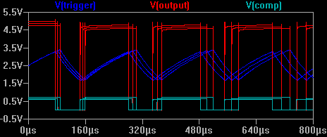
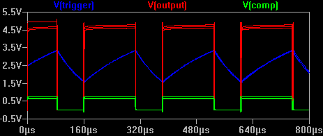
National Semiconductor made the changes to improve the performance of the comparators, specifically their performance over temperature. I ran some more simulations so you can see the difference. Here is the NE555 set up in a simple astable circuit, with superimposed waveforms at 0C, 35C, and 70C:
And the LM555 at the same temperature ranges.
Note that I put the temperature coefficients only on resistors inside the 555 timers, not on any of the external oscillator components.
If you want to play with the
LTSpice circuits, click the links below to download them.
A quick side note about the names: The LM in the part number stands for Linear Monolithic, which National Semiconductor used to describe many of their analog ICs. The NE probably stands for Network Electronics (the sources are anecdotal). Apparently the Signetics name came from Signal Network Electronics.



Graham Stratford :
Date: October 2, 2018 @ 12:01 pm
I built a latching relay driver with 555s. It puts our two 50 ms pulses of 12 V in turn. Leds indicate the presence of the pulse. In the second 555 there was an unwanted narrow pulse after the desired pulse sufficient to fire the led. By switching from an LM555 to an NE555 I was able to reduce the height and width of this unwanted pulse. Now the circuit should work fine.
Dennis Wheeler :
Date: June 2, 2022 @ 3:29 pm
The quote reference to “The 555 Timer Applications Sourcebook” is incorrect in this article. The quote is on page 72 (right after diagram figure 5-35 on the previous page). But the quote is referring to diagram figure 5-32 on page 70.
Also, its not table S-2. Its table 5-2 (also on page 70).
The book directly quotes and copies the diagrams from “Electronics” magazine of 19th Feb 1976, p.131.