Sound Blaster 1.0 Principles of Operation
January 19, 2019 Cleverness No CommentsThe Sound Blaster 1.0 was not the first PC sound card, but it was the first to support digital sound, two different types of sound synthesis, MIDI, and a joystick all in one card. Let’s lift the hood and examine how the card does its magic.
You can follow along by looking at the schematic here.
Sound Playback
There are three methods a Sound Blaster card uses to play back digital audio.
Direct DAC
The first is called Direct DAC and it means that the PC software has to feed the sound card each sample at just the right time. It works a lot like the parallel-port DACs that people used to build in the 80s and 90s, or like the Disney Sound Source. When you send a data byte to the sound card, it immediately changes the analog signal going into the speaker amplifier.
Software using this method typically sets up a periodic timer interrupt. In the interrupt handler, the new sample is calculated and then fed to the sound card for playback.
Although it’s a simple method, it produces extra noisy playback to due the timing jitter of the interrupt handler. Because PC interrupts are non-deterministic, the samples don’t occur at precisely the sampling rate. This timing difference means that the waveform being reproduced doesn’t match the source material, and the difference in voltage sounds like noise or hiss.
DMA DAC
The other method uses the DMA (Direct Memory Access) controller on the PC motherboard to automatically send samples to the sound card. It does require a little bit more work to set up the operation.
- The software configures the PC’s DMA controller (historically an Intel 8237) with the source address and length. The DMA controller is set to perform a single transfer per DMA request (DREQ).
- The Sound Blaster is configured for a particular sampling rate. It programs an internal timer to generate a DREQ signal at the sampling rate.
- The software sends the playback command to the Sound Blaster.
The next operations happen in a loop until all the samples have been played back. Notice that the software is not involved at all—just the DMA controller, the Sound Blaster, and main memory.
- The Sound Blaster asserts DREQ.
- The DMA controller responds by asserting DACK (DMA Acknowledge) at the same time it places the memory address and memory chip select onto the bus. The data byte gets transferred directly from main memory into the Sound Blaster input register!
- The Sound Blaster takes this data and sends it to the audio DAC.
Finally, the Sound Blaster ends playback then triggers an interrupt to let the software know that it is done with playback.
Auto-Initialize DMA DAC
The final method, introduced with the Sound Blaster 2.0, is very similar to the previous method, except the ending. The Sound Blaster triggers an interrupt as before, but then it reloads the sample counter to the original value and continues requesting samples from the DMA controller!
The usual way software uses this feature is to create a seamless digital audio stream using a double buffer. The DMA controller gets a buffer that is twice as big as the number of samples that the Sound Blaster is programmed to play back. Because of that, the interrupt gets triggered halfway through buffer playback. In the interrupt handler, the software then loads a new set of samples into the buffer half that has already been played. When playback hits the end of the DMA buffer, the interrupt triggers again, only this time the software refills the last half of the DMA buffer. The DMA controller then wraps around to the beginning of the buffer and playback continues unbroken.
One of the side effects of this approach is that if the software crashes, the DMA controller and sound card continue to play back the sample buffer in a loop. You may have heard this when playing old DOS games back in the day.
Sound Recording
This works in very much the same way as playback including the Direct mode, DMA mode, and Auto-Init DMA modes, except data gets transferred in the opposite direction, from the sound card into main memory.
One interesting wrinkle is that the Sound Blaster doesn’t actually have a proper ADC (analog-to-digital converter)! Instead it uses a clever circuit and an algorithm to accomplish the same thing:
- An input filter processes the incoming sound to smooth out any high frequency transients. This is common practice, even with an ADC, to help prevent sampling-induced aliasing, but it it’s helpful for making the trick work.
- A comparator looks at the difference between the audio DAC and the incoming signal. The output of the comparator is only one bit; it can only tell if the incoming signal is greater than or less than the setting of the audio DAC.
- The DSP starts the audio DAC at the halfway point, then looks at the comparator output. The comparator output gets recorded as the most significant bit of the audio sample.
- Depending on the bit, the DSP sets the audio DAC up or down half again—either 25% or 75%.
- The DSP repeats steps 3 and 4, going halfway again and again until it’s obtained the 8 bits of a complete sample.
This technique is known as successive approximation, and it’s a technique used in many ADC chips. The code looks something like this:
mov	p1,#80h		; Start DAC at the halfway point, 1000 0000

mov	c,t1			; 1 Put comparator output into carry bit

mov	p1.7,c			; 2 If greater, then leave MSB as is. If less, clear MSB

setb	p1.6			; 1 Set DAC to upper or lower halfway point

mov	c,t1			; 1 Check comparator output again

mov	p1.6,c			; 2 Rinse and repeat

setb	p1.5

mov	c,t1

mov	p1.5,c

setb	p1.4

mov	c,t1

mov	p1.4,c

setb	p1.3

mov	c,t1

mov	p1.3,c

setb	p1.2

mov	c,t1

mov	p1.2,c

setb	p1.1

mov	c,t1

mov	p1.1,c

setb	p1.0

mov	c,t1

mov	p1.0,c

mov	a,p1			; We are done, copy DAC code into accumulator.
The Hardware, Section By Section
Address Decoder
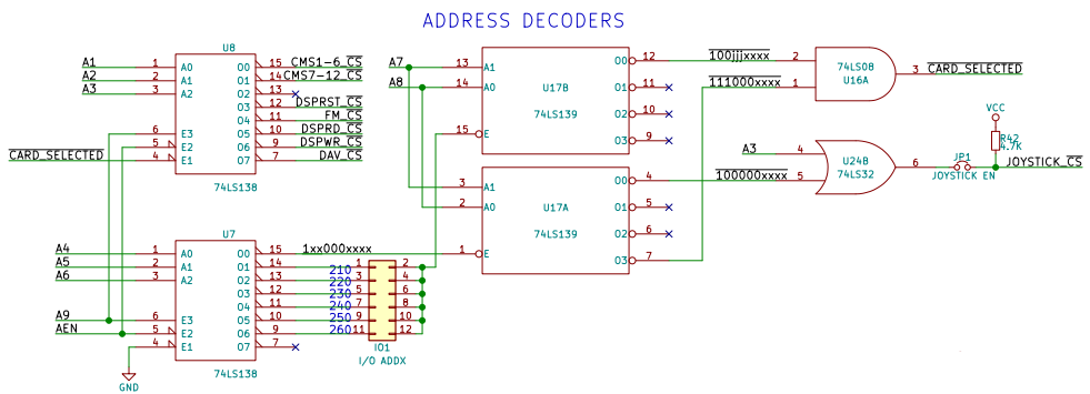
The address decoder takes the I/O port address off the ISA bus and looks for accesses at 210h, 220h, 230h, 240h, 250h, or 260h depending on the jumper setting. It also looks for 388h and 389h so that it can make the Yamaha OPL2 chip appear there for Adlib compatibility. It also decodes 0x200-207h as the joystick port (each address is actually the same).
A jumper, JP1, can be pulled to shut off the PC joystick port. The MIDI function still works, however. Many combo-IO boards came with a built-in joystick port so the one on the Sound Blaster may not always be needed.
Reset Circuit
It’s important to make sure the card powers up in a good state without generating spurious noises, so the SB uses the ISA RESET signal to clear the OPL2, the CMS chips, the joystick one-shot, and basically all of the other internal state latches.
There is also an IO port that, if you write a 1 to it, resets the DSP and its associated bus interface. (You also have to write a 0 to it afterwards to allow the DSP to start operating.) Later versions of the DSP require this to exit high speed auto-init DMA mode, since in this mode, the DSP devotes 100% CPU to servicing DMA requests.
DSP
The core of the digital sound capabilities of the Sound Blaster is the Digital Sound Processor, or DSP for short. It’s not actually a Digital Signal Processor in the traditional sense—it’s just an 8051 microcontroller with custom firmware.
The DSP also handles MIDI transmit and receive using the 8051’s built-in UART.
DSP Bus Interface
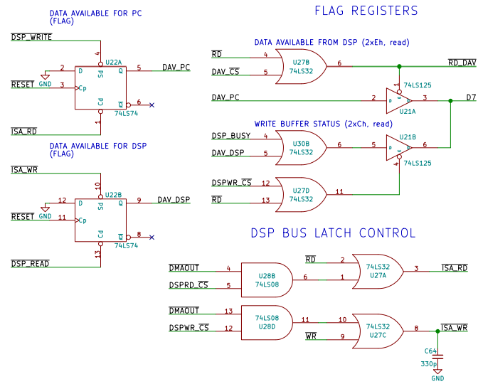
The bus interface allows the host PC to talk to the DSP. It uses two unidirectional 8-bit registers as a “mailbox,” temporary holding areas for a single data byte. One is for PC-to-DSP communications, and the other is for DSP-to-PC communications. There are also two data flip flops that are used to signal when data is available in one of the registers.
When the PC sends data to the DSP (I/O port 2XCh), the data gets stored in an 8-bit register and the flip-flop is automatically set high (DAV_DSP).
When the DSP reads the register, the flip-flop gets cleared automatically.
When the DSP sends data to the PC, the data goes into the other 8-bit register and the other flip-flop automatically gets set (DAV_PC). The PC can check this bit by reading from I/O port 2XEh. When it reads from I/O port 2XAh, it receives the byte of data and the flip-flop automatically gets cleared. The DSP can see that the PC has read the byte by checking the DAV_PC input. The DSP often checks this pin to make sure the PC has read a data byte before writing a new data byte to the register, otherwise the byte in the register will be lost before the PC has a chance to read it.
Interrupts
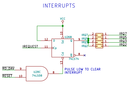
When the DSP is done with a particular (often lengthy) task, it can signal the host PC by asserting the interrupt line. It does this by pulsing IREQUEST which triggers a flip-flop that asserts the IRQ line on the PC bus. On the host PC, the interrupt handler is supposed to clear the interrupt by reading from I/O port 2XEh. This simply clears the flip-flop which then deasserts the IRQ line.
DMA
When the DSP needs a new sample from the PC (or needs to transfer a new sample to the PC during record mode), it pulses the DREQUEST line. Note that the DSP also needs to enable DMA by asserting its DMA_EN# line. When DREQUEST pulses, it causes the DMA request flip-flop to output a 1 on the DRQ1 line. The PC’s DMA controller responds by asserting DACK1#, which clears the flip-flop. DACK1# also bypasses the address decode logic of the Sound Blaster and forces it to either accept data from or place data on the ISA bus lines. This data transfer happens between the ISA bus and the mailbox registers.
Digital Audio Output
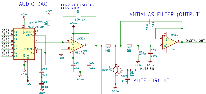
An 8-bit DAC connected to the 8051 generates an analog current corresponding with the digital code on its inputs. A current-to-voltage converter (U5C) changes the current into a voltage that is used by the rest of the circuit. This voltage goes through an antialiasing filter which removes distinctive- and ugly-sounding artifacts from the audio signal. U5A implements this filter using a Sallen-Key design. The filter cutoff frequency is about 4KHz, meaning that it’s designed to prevent aliasing for sample rates of 8KHz and above.
Next, the signal goes through an op-amp circuit which mixes the digital sound with the audio from the FM synthesis chip as well as the CMS chips. Unlike later Sound Blaster cards, the mixer is fixed and cannot be adjusted.
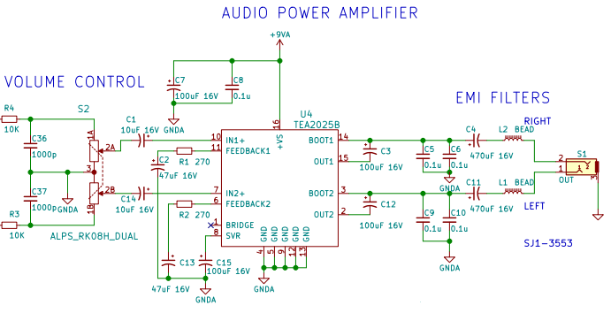
Finally, the signal goes through the volume control wheel and the built-in audio speaker amplifier before coming out the audio jack on the back of the card.
Since there is only one DAC, playback is mono, not stereo.
Audio Input
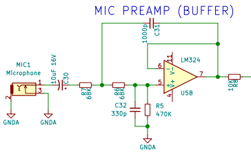
The Sound Blaster has a microphone jack on the back. It is only compatible with dynamic microphones or electret microphones that have built-in batteries because it has no bias power supply, unlike more modern sound interfaces. The input signal goes through a series DC-blocking capacitor and then into a preamplifier that converts the high impedance microphone signal into a low impedance signal needed by the rest of the internal circuit.
The preamplifier is also a Sallen-Key low-pass filter with a cutoff frequency of 4KHz. It is a 2nd order filter which means the attenuation increases by 40dB per decade. At 40KHz, the signal is down by 40dB.
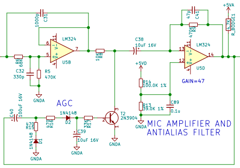
The signal passes through a gain stage that amplifies the low-level signal, then passes it into the AGC (Automatic Gain Control) circuit. This circuit rectifies the AC input signal and filters it into a slow-moving voltage that represents the average level of the output (an envelope signal). This signal goes into a transistor that can attenuate the gain stage’s input signal level if it gets too high.
The gain stage uses an LM324 with a gain of 47 (about 17dB). Looking at the LM324’s datasheet, that gives us a bandwidth of about 30-50KHz. A small feedback capacitor (C41) makes this amplifier a single-pole low-pass filter with a cutoff frequency of 7.2KHz.
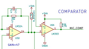
This filtered and amplified input signal goes into one input of the ADC comparator. The other comparator input comes from the audio DAC which generates the successive approximation signal.
There is something missing from the circuit, however. A true successive approximation ADC uses a sample-and-hold circuit to prevent the signal from changing voltage during an acquisition cycle. The Sound Blaster cheats and just pretends that the antialiasing filter will slow the signal down enough. It’s probably a bit noiser than it could be.
During ADC sampling, the DSP activates a mute circuit that prevents the successive approximation signal from bleeding out into the speakers, which is important because it would sound terrible! Because the audio DAC is used for both playback and recording, the Sound Blaster is only half duplex and cannot play back audio at the same time it is recording it.
MIDI I/O
The DSP, since it is just an 8051, has a built-in UART. The DSP firmware configures the UART for the MIDI baud rate (31250) and handles the MIDI messages.
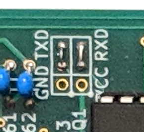
There is a jumper bank just above the DSP that has some wires installed instead of a normal 0.1″ header pin array. The shorting wires route the UART RX and TX lines from the DSP out through the joystick connector. If the wires were removed, then a serial cable could be installed on the headers. I suspect this is how the engineers at Creative Labs debugged firmware issues.
To use the MIDI I/O with standard MIDI devices, you have to use a special adapter cable that includes the optoisolators required by the MIDI standard.
FM Synthesis
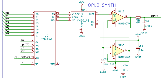
Two Yamaha chips produce FM-synthesized sound. The famous YM3812 OPL2 chip generates a digital serial PCM signal that gets converted into an analog waveform by the YM3014B DAC. The OPL2 chip has already been described extensively elsewhere.
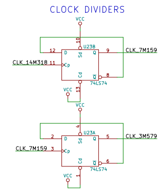
One interesting thing is that the Sound Blaster uses two daisy-chained flip-flops to divide the ISA bus’s 14.318MHz clock signal down to 3.579MHz for use by the OPL2 chip.
To sum up, this part of the Sound Blaster behaves exactly like an Ad Lib sound card. Since there is only one single-channel YM3812, the FM synthesis output is mono.
CMS Music
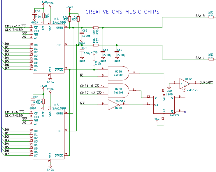
The CMS (Creative Music System) chips are actually Philips SAA1099 audio chips.
The clock signal for these chips comes from a 7.159MHz signal which is just the ISA 14.318MHz clock divided by two. It’s a tap off the same clock divider chain used by the FM synthesis chip.
These two chips generate a left and a right channel, and they’re the only source of stereo sound on the Sound Blaster!
There is a flip-flop, U20B, that drives the ISA bus’s IO CHRDY signal to lengthen the host PC’s bus write cycle for the SAA1099 chips because they are quite slow.
Joystick Circuit
Here’s another place where the Sound Blaster cheats and doesn’t use an analog-to-digital converter. Just like the IBM joystick card (and clones), it uses an NE558 (the “quad” version of the classic 555 timer) as a variable one-shot timer. Each joystick axis is a variable resistor, that, along with a fixed capacitor in the Sound Blaster, controls a time delay. Writing to the joystick port triggers all four timers (one per joystick axis). The software then polls the joystick port and times how long it takes for each axis to reset. The time delay correlates with the position of the joystick.
In the above capture, the circuit has been connected to a resistance of 38.1K. Since the fixed capacitor is 0.01uF and the 558 threshold voltage is 2/3 of 5V or 3.33V, we get a time delay of about 420us.
Conclusion
The Sound Blaster 1.0 met a market need for a low-cost sound card with lots of features and backwards compatibility. It supported digital sampling using some clever hacks to keep the costs down, worked with all existing software that supported the Ad Lib sound card, and even integrated joystick support and MIDI functionality. No wonder the Sound Blaster series became the most popular sound card of all time!
If you want to try one out in your retro PC, consider building my replica design, the Snark Barker. The design files are available at my GitHub repository.

