Panaplex Wall Clock Schematic and Software
April 28, 2012 Uncategorized No CommentsRemember my Panaplex clock project? Here’s a present: the design details!

Remember my Panaplex clock project? Here’s a present: the design details!
Wow, it’s been a few months since my last post. Sorry for the blog silence. I got very busy with a new job and just haven’t had the time to work on projects at all, let alone blog!
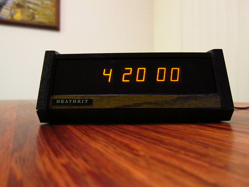
So here’s a quick one–it’s a Heathkit GC-1005 digital clock that uses Panaplex displays (Neon filled). I picked it up at the electronics flea market and it looked like someone had been trying to get it working before me, and they left a bit of a mess. I had to clean up the wiring job and check the electrolytics to make sure they were still good (they were).
The reason it wasn’t working right is that some of the component leads on the bottom of the PC board had poked through a paper insulator and shorted out against the switch contacts on the bottom of the case. All I had to do was trim the component leads and fix the insulator.
At Maker Faire, a lot of people asked me if I had a kit available for any of my CRT clocks. Based on the amount of interest, I’ve decided to put together a kit that will make it easy for people to drive cathode ray tubes using simple digital or low voltage analog control signals. The kit will include a PC board and all the components as well as detailed assembly instructions. For people that opt to use the digital interface, the kit will also include source code libraries making it easy to generate simple vector graphics.
The kit will use surface mount components, but none smaller than 0805. The ICs will be SOIC or SOTs, with the exception of the DAC, which is TSSOP.
Because this would be the very first surface mount kit many people attempt, I’m trying to figure out an approach for the assembly instructions that will make it easy to succeed. Some ideas I’ve had so far are:
Hobbyists seem to have an aversion for surface mount components. With a little practice, I’ve found that it’s faster and easier to use surface mount components. Think about all the time you could save by not having to bend and clip resistor leads. You can solder most of the components without having to flip the board over.
If you have any ideas, please feel free to comment. This is all still in the early stages so there is plenty of room to change things and try new approaches.
The Maker Faire is a neat DIY convention that happens every year. I’m bringing some of my projects to the Maker Faire Bay Area; just look for Tube Time. Come and say hello!
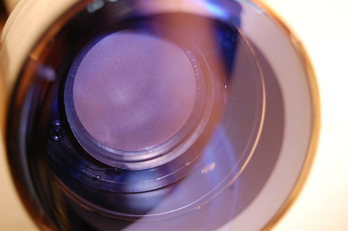
The other day at the electronics flea market I obtained a couple of new CRTs. The one below has a P2 phosphor which is brighter and more energetic than the P1 and has much longer persistence. You can light it up with one of those UV LED flashlights. Notice the inspection sticker.
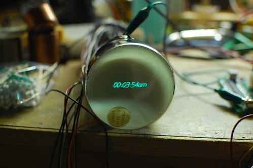
And the one below is a fine example of the P12 phosphor–it lights up amber. The color is similar to that of the old amber MDA monitors but the persistence is longer.

Hello to everyone from the Maker Faire! It was great meeting you all in person. But if you missed out, here are a couple of pictures to give you an idea of what the event was all about:
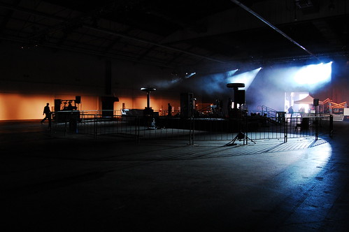
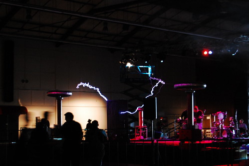
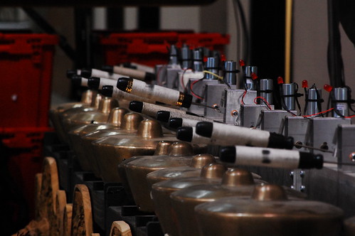
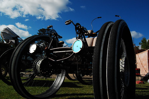
There are many more pictures in the MAKE Flickr Pool. The entire San Mateo expo center was jammed with crazy, cool, weird, and wild exhibits, projects, vehicles, and people!
My friend Jeri recorded some video of my exhibit, so take a look if you couldn’t make it to the Faire.
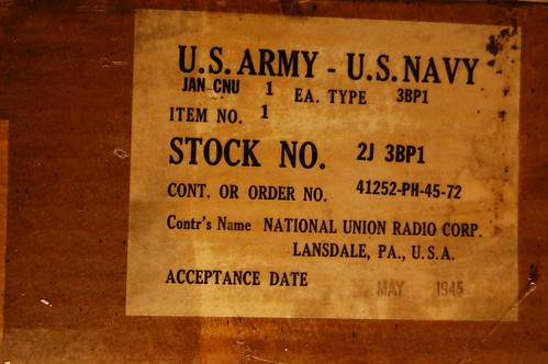
Yesterday I went to the local electronics flea market and picked up some interesting items. The first is a 3BP1 3″ round cathode ray tube. It was in the original box which was still sealed and coated with wax.
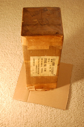
The label indicated that the tube was manufactured in 1945.
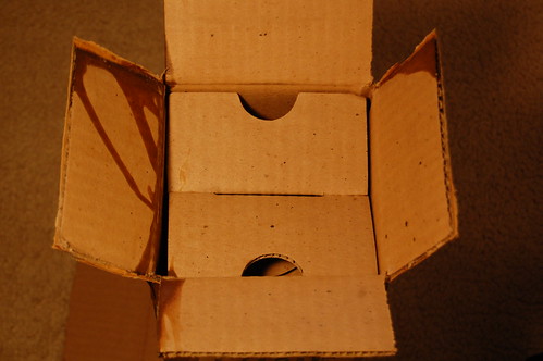
Of course I needed to open it to make sure the tube was intact. Many times these tubes are stored upside down, and often fragments of various internal parts will break off due to vibration, fall down, and ruin the phosphor screen.
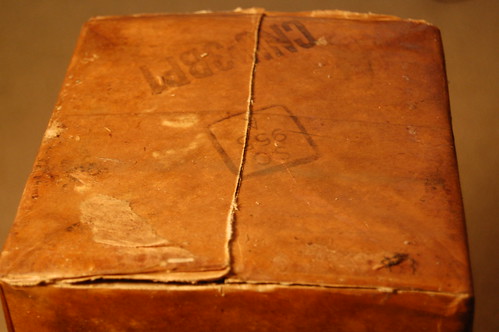
I half-expected an Indiana-Jones-style puff of ancient air as I broke the seal.
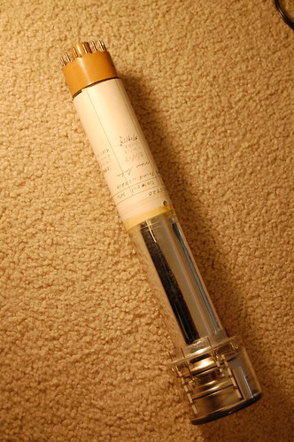
And yes, it’s in perfect condition. The outside of the tube is slightly dirty but these tubes really didn’t need to be cleaned before leaving the assembly line to work properly.
The next find is an RCA 5820 Image Orthicon tube. This tube came in the original box which indicates that it was shipped to KGO-TV in San Francisco in 1953. It would have been used in the RCA TK-11 TV camera which was very common at the time.
This is a closeup of the front.
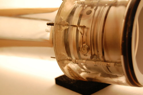
And here you can see the internal elements. The round bit in the middle is actually a very fine mesh screen.