In December 1989, Creative Labs launched the now-famous Sound Blaster card. Almost 30 years later, I’d like to announce the Snark Barker, a replica of the original card designed to satisfy all your retrocomputing cravings!
Don’t get too excited though because it’s not complete. Well, the board layout and schematic are fine, but there are two chips on the board that are special.
The HD6801VD855P (Roland part number 15179222) is a mask-ROM microcontroller that runs the entire card. I’m not aware of anyone who’s dumped the ROM, but maybe now there is an incentive to do so. 😉
The HG62E08R10FS (Roland part number 15239133) is a gate array device. Think of a CPLD but these were “programmed” by customizing the top layer of metal during the IC fabrication process. Roland calls it the “Handshake controller” but nothing is known about the internal logic. If someone sacrifices a card and decaps this chip, a simple image of the top metal should be enough to deduce the functionality. There are rumors this chip is used on other Roland cards, but I am hesitate to say they are identical. I suspect Roland had various versions of this chip with different logic depending on the card and the computer’s bus. More work needs to be done.
Anyway, I hope this is useful to someone out there!
Today is an exciting day for people who collect vintage IBM PCs and XTs! IBM had a somewhat obscure add-on product called the 5161 expansion chassis, which looked exactly like an IBM PC but with a difference case badge. It allowed customers to add two additional full-height drives (typically 10MB MFM hard drives) and 7 usable expansion slots (excluding the one used for the MFM disk controller). And yes, with those full-height hard drives, it sounded like a jet engine.
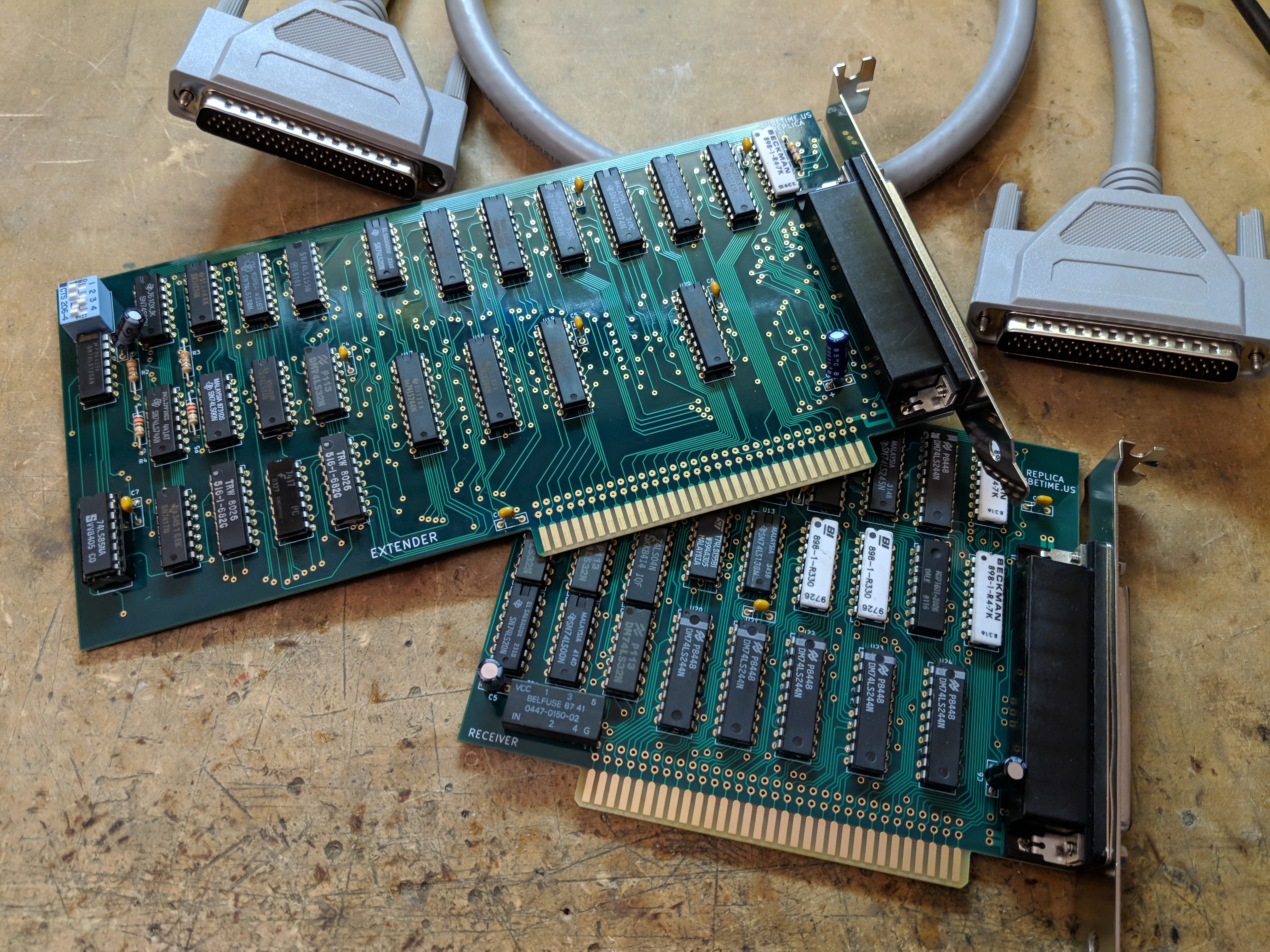
Connecting the expansion chassis to the host PC were two expansion cards. One, the extender, was placed in the host PC. The other, the receiver, went into the expansion chassis. A 62-pin D-sub connector tethered the two together.
One small problem: with the few remaining 5161 units, the extender card was typically separated and lost. Often the connecting cable was as well. If you got lucky, you might find a PC with the extender card still in it. Regardless, people often own more expansion chassis than extender cards, making them useless. Until now.
Based on careful study of high resolution photos of the cards and the schematics published in the IBM technical reference manuals, I’ve been able to design duplicates of both the extender and receiver cards. Details are in my GitHub repository.
Even if you don’t own an IBM 5161 (and I don’t blame you, it’s a bit obscure!), you might still find the cards useful. The receiver card works fine in common passive ISA backplanes! One small caveat: The backplane in the 5161 provides the 14.318MHz OSC signal which many ISA cards need. Passive backplanes do not provides this signal. You can check edge contact B30 on the back of the card edge. If there’s a missing contact or a contact that doesn’t connect to a trace, the card should work.
This card also needs some initialization to function. The BIOS in the PC/XT take care of this automatically, but this may not be true for all BIOSes. I’ve only tested it in my IBM PC. Even so, it may be possible to get it working by poking at the card’s I/O ports.
Before I put together a long term solution, I wanted a quick way to transfer software from my PC to my Commodore PET. There are other circuits, but I wanted something that used just one part.
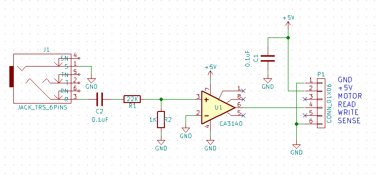
The PET input is TTL level, so I needed something to go from audio level to TTL. Ideally a comparator circuit with plenty of gain. Well, I couldn’t find a decent comparator in my junk box, but I did find a CA3140 op-amp. This is way faster than I needed, but should work OK as a comparator. If you build this circuit, try to find a comparator or an op-amp with a rail-to-rail output.
Here is the circuit:
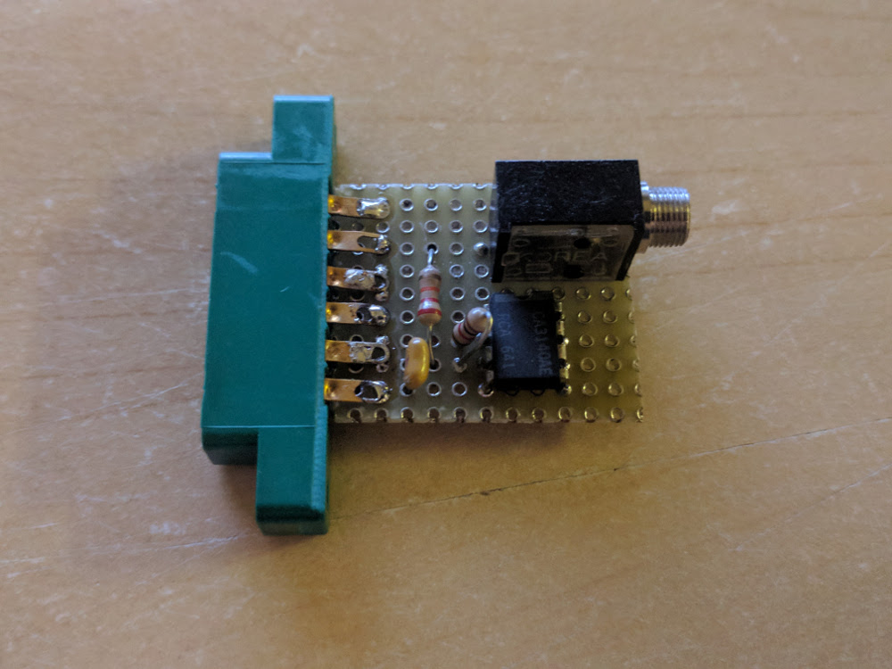
And here’s what it looks like:
It works quite well. The circuit is not very sensitive to the output audio level from the PC–I set mine halfway (line level) and it was fine.
Edit: Someone who goes by W9EO has recorded assembly videos on YouTube which you may find helpful for building this card. He is also selling completed cards if you don’t want to solder it yourself.
Growing up, I used to play some games on an AST 286 computer, including Commander Keen, Wing Commander, and a few others.
Sound in those days was primitive compared to modern machines, but I still have a soft spot for the bleeps and bloops of the OPL2 synthesizer cards (which includes the AdLib).
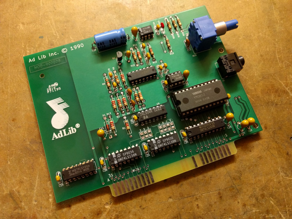
Recently I have been fixing up an IBM XT (with original CGA card!) and I needed a sound card. It turns out that early sound cards like the AdLib or the Sound Blaster are quite expensive on the used market, so I thought I’d make a clone of the AdLib sound card (1990 version). Being me, I couldn’t just make an electrical equivalent. It had to look as close as possible to the real thing.
I started with Sergey’s OPL2 card and corrected some differences between it and the genuine AdLib card. Since I don’t own a physical card, I found photos on the net of the front and back of the card to use as a reference. To make sure everything matched up exactly, I figured out the design grid of the original and duplicated the traces and component placement as closely as possible. All the library footprints are custom designed to match!
The KiCad design files are available on GitHub. Mouser part numbers are embedded in the KiCad design but they are also included in the table below. The Yamaha OPL2 chipset, the YM3812 and YM3014B pair, can be found at various sources online. They were socketed on many older Sound Blaster cards, so I suspect quite a few were recovered by the scrappers.
Q
Designator
Description
Mouser Part
1
J1
CONN_01X05
490-SJ1-3553NG
1
U6
YM3812
11
C4,C5,C24,C2,C25,C20,C19,C26,C1,C14,C16
0.1uF
581-AR215C104K4R
1
D1
D
512-1N4148
1
Q1
2N3904
512-2N3904BU
2
R1,R13
8.2K
291-8.2K-RC
6
R2,R3,R6,R7,R11,R12
2.2K
291-2.2K-RC
1
R4
12K
291-12K-RC
4
R5,R9,R10,R16
10K
291-10K-RC
1
R8
1.5K
291-1.5K-RC
1
R14
POT
652-91A1A-B24-D15L
3
R15,R18,R19
10
291-10-RC
1
U1
74LS109
595-SN74LS109AN
2
U2,U3
74LS138
595-SN74LS138N
1
U4
74LS245
595-SN74LS245N
1
U5
74LS04
595-SN74LS04N
1
U7
YM3014B
1
U8
RC4136
595-RC4136N
1
U9
LM386N
926-LM386N-4/NOPB
1
C18
220uF
647-TVX1C221MAD
4
C7,C6,C9,C8
4700pF
581-AR211C472K4R
1
C12
1000pF
581-AR211C102K4R
1
C17
0.047uF
581-AR215C473K4R
1
C13
270pF
594-S271K43SL0N6TK5R
6
C23,C21,C22,C11,C3,C15
10uF
581-TAP106M025CRW
1
C10
4.7uF
581-TAP475K016SCS
1
MNT1
CONN_01X01
534-9202
To install the card in a computer, you’ll need to get a Keystone 9202 bracket. The KiCad layout includes a drawing showing where the holes need to be punched in the bracket. I recommend using a hand-held sheet metal punch with a 7mm or 9/32 die. You could also drill it but the punch makes a much cleaner hole.
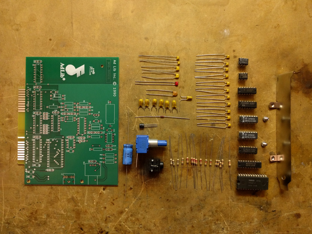
Here’s a bonus photo showing all the parts laid out before soldering. The components were chosen to match the colors on the original card.
I’ve uploaded the design files for my CRT deflection yoke driver board. This works for CRTs that use magnetic deflection. For a complete design, you will need the following boards:
ScopeVideoOnly – Video amplifier, focus chain, and nothing else (the ScopeDefl electrostatic design combines this amplifier with the electrostatic deflection amplifiers)
Gerbers are in the repository but you can get them directly from OshPark by clicking the links for each board above.
This board, unlike the others I’ve developed so far, requires both +12V and -12V. My projects typically use an Artesyn NFS40-7608J but it is now obsolete and a bit expensive, so you probably should use something else for power.
There are places on the board (C6/R9, C10/R20) for coil compensation components. You can figure out the values that you need with a little experimentation.
The board is designed for a vector-style yoke, not the far more common raster scan yoke that has a high inductance vertical deflection coil with lots and lots of turns. It can usually drive the horizontal coil no problem, but you’ll want to modify the vertical winding to reduce the number of turns. Check out my blog post on winding deflection yokes for more information on making your own.
The LM4765 audio amplifier, which drives the deflection coils, will dissipate a lot of heat so you will need to bolt it onto a good-sized heat sink (at least 3″ x 3″ aluminum with fins, not some dinky little TO-220 clip-style heat sink).
Circuit operation is pretty straightforward. CRT electron beam deflection is proportional to the magnetic field which is proportional to the current in the coil, so the LM4765 controls the coil current (measured through R14/R25) instead of the voltage. The current is therefore directly proportional to the input voltage (X or Y). An extra gain stage facilitates the width/height and left/right offset adjustments.
At the electronics flea market I recently found something particularly interesting…
This is a vintage Philbrick K2-W vacuum tube operational amplifier! Turns out they have quite the following. Sadly the original 12AX7 tubes were gone–somewhere, someone probably has rare GAP/R marked tubes in their guitar amplifier. I put in some generic replacements.
I decided to build a little jig to try it out.
This is based on the inverting amplifier schematic given in the K2-W datasheet I linked above. I added a simple linear power supply to generate the +/-300V rails. If you build your own supply, be sure to add bleeder resistors so you don’t get a nasty surprise after you turn it off and try to work on it.
After connecting a 10K series and 100K feedback resistor to the op-amp, I ran a 1KHz 5Vp-p square wave from my function generator into the circuit and saw this:
Neat! The top trace is the input and the bottom trace is the output. The bottom trace has a magnitude of 50Vp-p, as expected.
It’s really interesting to see how the short paragraph of specifications at the bottom of the first page of the K2-W datasheet developed into the formal electrical characteristics tables you can see in more modern op-amp datasheets, like the 741.
If you build either of those and try it out on an STM32F407 Discovery board, you will notice that no sound comes out. The reason is that the onboard audio codec has a LRCK line (left/right framing clock for the I2S audio stream) wired up to GPIO PA4, which happens to be one of the DAC outputs that we are using for the vector graphics generation. You’ll need to disconnect LRCK (U7 pin 40) from PA4 and wire it to PA15. I did it by cutting a trace (indicated with a black arrow) on the back of the board to isolate the PA4/LRCK net from the STM32:
And by adding a wire (indicated in red) on the top of the board from R48 to pin 77 (red arrow) of the STM32 (PA15):
Oh, and one more thing. To keep the audio mixer marching along, we had to connect PC6 to PC7. This ties the I2S MCLK to timer 3 channel 1, which triggers a periodic interrupt that mixes new samples into the audio output buffer. The easiest way to do this is to connect a jumper across pins 47 and 48 on the GPIO header P2. They are clearly marked on the board and the pins are right next to each other so this is easy.
If you follow me on Twitter, you’ve probably seen the picture of a CRT deflection yoke undergoing surgery. Well, it’s now installed in a mini Battlezone arcade cabinet that I built for Maker Faire this year.
It uses a 5-inch B&W CRT taken from a broken security camera monitor. I had to rewind the yoke to make the vertical windings fast enough to handle vector graphics. The horizontal windings were already pretty close, but they did need to be rewired to operate in series to reduce the drive current.
The CRT is a bit different than most of the old-style CRTs I work with. For the curious, it uses an EIA E7-91 style base which has an additional grid for acceleration purposes. The lower circuit board in the photo is a potentiometer resistor divider that develops a ~300V bias voltage to drive this additional grid. The upper board is a Cockcroft-Walton multiplier circuit to step up the 1KV power supply voltage to the 4KV necessary for the post-deflection acceleration (PDA) anode. I’m running this CRT a bit under voltage, and it works fine because I’m not trying to fill the whole screen with a solid raster.
The metal enclosure houses the power supplies–it is made out of soft steel with the idea of containing the stray magnetic fields generated by the power supply switching inductors. It works a bit, but I’ve had better luck in the past with mu-metal shields around the CRTs themselves. There are three power supplies: one steps 120V down to +12V, +5V, and -12V. Another steps +12V to +1KV, and the final one steps +12V up to +60V. These last two power supplies are detailed here. They are open-source hardware so you can build your own.
Outside the shield you can see the video amplifier board at the lower left, which is the same circuit used on my electrostatic deflection board but without the deflection amplifiers. At the bottom right is my new magnetic deflection amplifier board which drives the deflection yoke. It is based around an LM4765 audio amplifier IC. I’m not totally happy with the design but eventually I will release the board design. The green board in the upper middle is an STM32F4 Discovery board. The board to the right of it is an audio amplifier that drives the speaker.
The joysticks I machined out of small aluminum blocks. It took some experimenting to figure out how to arrange the springs to get the joystick to return to the center position. The joystick handle on the right is hollow to allow the wires for the fire button to pass through.
I also build a second unit with the same driving circuit but a different CRT–a 5-inch round 5AXP4. This CRT would originally have been used by a TV technician to look for problems with the chassis or the full size picture tube in a customer’s set. The glass is extra thick because the tube was designed to be handled more. This is the same tube that I started experimenting with last year.