Tiny CRTs in Action

Projects No Comments

Richard built up some of my CRT driver boards and put them to use, testing a variety of CRTs with interesting characteristics, such as the rare 1DP11 or the vintage RCA 913.

He’s also got a nice video as well:

If you plan to build up the CRT boards, I highly recommend you visit Richard’s page. He’s drawn up an excellent connection diagram that shows how to interconnect the HV power board, the video power board, and the deflection/video amplifier board.

Miniature Nixie Power Supply – How it Works

Projects 1 Comment

For more details and the video about the miniature Nixie power supply, see my original post.

First off, this circuit is not a Royer oscillator. As summarized by Jim Williams in his famous app note AN65, Royer developed a power converter using a transformer that saturates every cycle.

A coil saturates when the magnetic field (the B field) has reached the maximum that the magnetic core material can support: if the current (which is what creates the magnetizing H field) increases more, the magnetic field increases very little. The inductance, which is proportional to (B ÷ H), rapidly drops off, causing the current in the coil to increase at a much faster rate. Royer’s design detects this current spike and uses it to switch the transistors (2N74s, in his original paper) into their opposite state.


My circuit is a more common LC resonant converter. There are two transistors, Q1A and Q1B. Resistor R1 provides the bias current for the transistors and gets things started. Current (represented by the large red arrow) flows through the center tap of the coil T1 out to Q1A through its collector. The current in the upper half of coil creates a magnetic field, and the magnetic field induces a voltage in the feedback coil. This voltage reduces the base drive for Q1A and increases the base drive for Q1B (represented by the small blue arrow). When that happens, Q1A shuts off and Q1B turns on. The current in Q1B’s collector (represented by the large blue arrow) creates a magnetic field of the opposite polarity in the coil, and therefore causes the feedback winding voltage to reverse polarity (see the small red arrow), turning off Q1B and turning on Q1A. The cycle repeats as long as there is power.


Above are some approximate waveforms. You can see that the transistors go back and forth, driving the coil first one way and then another. Capacitor C1 and inductor L1 help determine the resonant frequency of the circuit. If you measure the voltage across the entire coil, you’ll see a sine wave.

The output winding of the coil has a lot more turns than the input winding, and it increases the voltage (at the expense of the current) dramatically. This high voltage AC goes through the half wave rectifier formed by D1 and gets filtered to DC by C2. R3 limits the current into the Nixie tube.

You might be wondering why T1 is actually an inductor–an 8.2 millihenry one. It just makes the project easier to build. You only have to wind 12 turns on an off-the-shelf part instead of buying a hard-to-find transformer core and adding all the windings yourself.

If you feel so inclined, try adjusting the component values. Start with C1 and then maybe R1 or even L1. Try changing the number of turns on the coil.

Miniature Coin Cell Nixie Tube Power Supply

Projects 35 Comments

Update 11/3/2014: Fixed the coil connections on the schematic, along with the inductance. Also, check out this post to see how the circuit works.

This project has been a long time in progress. It started years ago at a Maker Faire where I built a Nixie tube pendant powered by a lithium coin cell battery. Since then, I’ve decided to make a PC board and put together some instructions on how to build such a power supply yourself. These little supplies are great for steampunk jewelry or possibly single-digit Nixie tube clocks (they’re not quite strong enough to drive multiple tubes). The battery life should be around 3 hours or so for a CR2032 lithium coin cell.

The schematic is below–click for a larger view. The bill of materials is located here, including Mouser Electronics part numbers. If you decide to order, get at least 5 of each part just in case you lose or burn up some of them.  Note: Mouser seems to be out of stock for the T1 inductor, but Digikey has it here.

Q1 is a single device; it actually contains two transistors which is why it looks like that on the schematic.

To make it easier to build, I’ve put up a convenient OSH Park project page link so you can order boards. When I ordered from them, it cost $2.80 for a set of three boards (with free USPS shipping). Not a bad deal at all!

When you have boards and components, there’s a specific order of assembly that makes things a bit easier. See this YouTube video:

Basically you need to assemble the components in the following order:

  1. Solder C1.
  2. Solder Q1. Be sure you line up the beveled edge with the extra-wide silkscreen. If you put it in backwards the power supply will not work.
  3. Flip the board over.
  4. Solder D1, then R2, and then C2. C2 is 0.01uF, similar to C1, but it has a 250V rating. It is very important not to mix these up.
  5. Solder R1, and then T1 (the big coil, not marked on the silkscreen).
  6. Take a piece of 32 gauge magnet wire that is 13 inches long and tin about 1/8 of an inch at one end. I use a soldering iron to burn off the varnish. Solder it into the upper left through hole that is below the coil.
  7. Wrap 5 turns clockwise around the coil T1. Thread the end of the wire into the middle through hole below the coil.
  8. Turn the wire around and thread it back through the same hole, pulling it tight to form a tiny loop. Solder the loop to the through hole.
  9. Take the wire and wrap another 5 turns clockwise around the coil. Thread the end through the top right through hole below the coil, and solder it in place. Trim off any excess.
  10. Get another piece of 32 gauge magnet wire that is 5 inches long, and tin about 1/8 of an inch at one end. Solder it into the lower left hole that is below the coil.
  11. Wrap 2 turns clockwise around the coil T1. Thread the end of the wire through the lower right through hole that is below the coil. Solder it, and then trim off any excess
  12. Solder the inductor L1. The reason it needs to be soldered last is that it makes it hard to wind wire around the coil T1.
  13. Solder connecting leads to the +, -, and OUT terminals.

To use it, connect a coin cell’s negative terminal to “-,” the coin cell positive to “+,” and “OUT” to the anode of a Nixie tube. The Nixie tube cathode goes to the coin cell negative terminal. Don’t touch the “OUT” terminal–you could get a shock. In fact, if you build the power supply into jewelry or something people will be touching, insulate all the connections.

Have fun!


A Miniaturized Discrete MC1466

Cleverness, Projects 15 Comments

Update: the bill of materials is now available. You can order boards from OSH Park using this direct link. Last time I ordered, it cost me a grand total of $3.55 for three boards (free shipping), and it took about two weeks for the boards to arrive.

I screwed up. My bench power supply is a Lambda LPT-7202-FM triple output (0-7V @ 5A, 0-20V @ 1.5A, 0-20V @ 1.5A), and I blew it up by trying to desulfate a lead-acid battery. The idea is to take a dead lead-acid battery and recondition it by charging it with a current-limited 15V source while feeding it high voltage pulses. I had a diode connected in between the battery and the bench supply to protect the power supply from the high voltage pulses. Well, the diode failed. It was a sad day.

Fortunately the service manual for the supply is available online. I traced around the circuit and found that two of the power control chips were fried, but everything else seemed OK–I could move the one remaining functional chip from channel to channel to confirm that. The control chips were marked with the Motorola logo and a Lambda house part number: FBT-031. A forum thread indicated that the part was actually the MC1466. Sadly this chip is long out of production and a bit hard to find, although a popular auction site had several listed from a seller in China (but who knows if the parts were counterfeit or not).

The datasheet has the full schematic including resistor values, but how do I know that it actually matches the chip? Since the IC is packaged in a ceramic DIP, I followed reader Uwe’s suggestion and took a chisel to one of the dead parts.

It worked and nothing was damaged! The die looks like this:

I went over the layout and it matches up with the datasheet schematic. Those funny round elements are actually zener diodes. You can see the long skinny resistors and the lateral PNPs as well as the NPN transistors and diodes. Below is the schematic (click to enlarge):

The IC design is pretty archaic. I’d say it dates to the late 1960s. There are fairly ordinary differential amplifiers, but the current mirrors are really strange, and the voltage reference circuit uses Zener diodes and series-connected diodes instead of a temperature compensated bandgap reference. The two Zener diodes (the only round features on the die) are probably just reverse biased NPN transistors, using the ~7.5V avalanche breakdown of the base-emitter junction. The lateral PNPs have a much higher breakdown voltage so they can’t be used this way.

Here’s a labeled die photo (click for a larger image) so you can see where each of the components are. The component designators match up with my schematic, not the IC datasheet schematic.

The device is simple enough that I decided to build a really small PC board with discrete components. I found that the BC847BVN (NPN/PNP dual transistor), BC847BV (dual NPN), and BAS16VV (triple diode) came in a really tiny SOT-563 package. Believe it or not, this is not the tightest or smallest layout I’ve done. This is a 2-layer board with 6 mil traces and 6 mil spaces.

To give you an idea just how small the SOT-563 is, take a look at the first BC847BVN I soldered:

The part is 1.05mm x 1.05mm! I had to use a very fine soldering iron tip and a microscope. Another trick is to use really thin solder (I used 0.38mm). As you can see, the resulting board is just slightly larger than the original DIP IC:

It really is pin compatible. I plugged two of them into my Lambda supply and now it works perfectly!

Compensating CRT Deflection Coils

Projects 16 Comments

Things look really weird when you use an uncompensated deflection coil with a vector graphics display. This is because the coil looks like an inductive load to the driver amplifier, and the parasitic capacitance makes it ring. Ringing and overshoot create the strange-looking display, basically extending every line past its destination.

One way to compensate for that is to add a series RC snubber in parallel with each deflection coil. You can perform some calculations to figure out the values of the resistor and capacitor but they won’t get you very close to the answer. There are just too many parasitics to model. It’s much faster just to build a RC substitution box and tweak the values until you get the result you want.

Electrostatic CRT Driver Design

Projects 61 Comments

Update 23-December-2014: Richard at LabGuy’s World has wiring diagrams for the RCA 913 and the 3JP7, and other neat stuff.

Update 23-June-2014: Please see the CRT Board BOM Updates page for important changes.

Update 3-June-2014: Added OSH Park links so you can order PCBs easily and quickly!

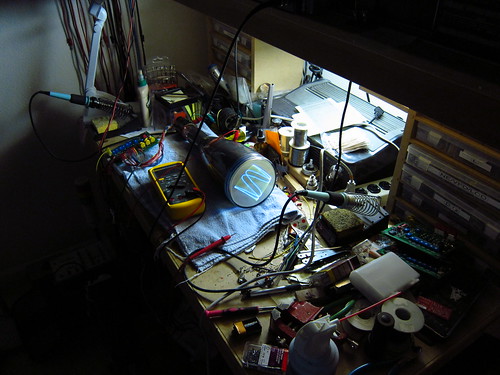
Well, it’s here! I’ve put together an open source release package for my CRT driver design. See all the glorious details at the GitHub project. It contains the fab data (Gerbers, NC drills, etc) as well as the CSV-formatted bills of materials for three boards. All the parts are available at Mouser Electronics (and the Mouser numbers are listed in the BOM). It’s the same set of boards that I used for my Asteroids and Flappy Bird arcade machines at Maker Faire.

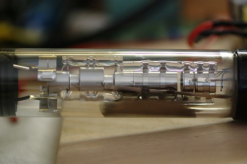
The design can drive most 2″, 3″, and some 5″ electrostatically-deflected cathode ray tubes, such as the popular 3BP1 or the precision 3RP1A. It can be modified to drive some of the oddball 2″ and 3″ CRTs that have a shared heater and cathode connection.

The three boards are:

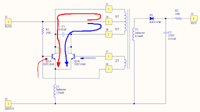
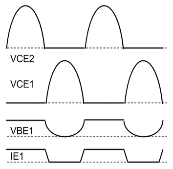
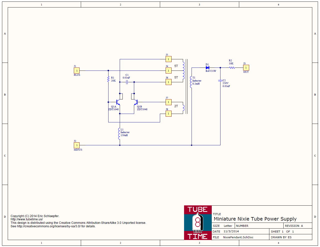
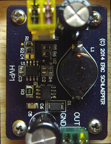
The 1KV power supply takes +12VDC and uses a Royer oscillator with an off-the-shelf CCFL transformer to create filtered 800-1200VDC. The voltage is tuned by adjusting R1. Use a plastic-handled pot tweaker tool please! The supply can easily source several milliamps, which at 1KV could stop your heart. This is a serious power supply, so please be safe if you decide to build it. Keep one hand in your pocket while using it. Turn the supply off before poking at it, waiting at least a second or two after switching off the DC supply to allow the sense resistor divider to bleed off the output voltage. Don’t work alone.
ps_board
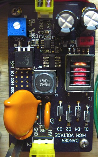
The design is inspired by CCFL circuits designed by Jim Williams–see the very long and wonderful AN65, especially Jim’s hand-drawn notes at the end. While Jim used a switching regulator to drive the Royer circuit, I used a simpler linear FET approach which works well but generates more heat. You will need to screw a metal heat sink to the plated through-hole located above Q1. Use a mica washer and a nylon screw if you want electrical isolation since this node is NOT ground.

If you want to put this in an enclosure, keep a clearance gap of 1cm or more between HV connections and low voltage nodes or a metal chassis. The power supply produces stray magnetic fields that will cause the electron beam in a CRT to deflect in ways you don’t want, so you should keep it far away from the CRT and use a CRT shield made out of high magnetic permeability material, like mu-metal or soft steel.

You can also add a voltage multiplier circuit, tapping in to diode D1, to generate post deflection acceleration (PDA) voltages. A 2-stage multiplier (as shown on the schematic) can generate 3KV which is fine for 3″ and 5″ tubes that require it.

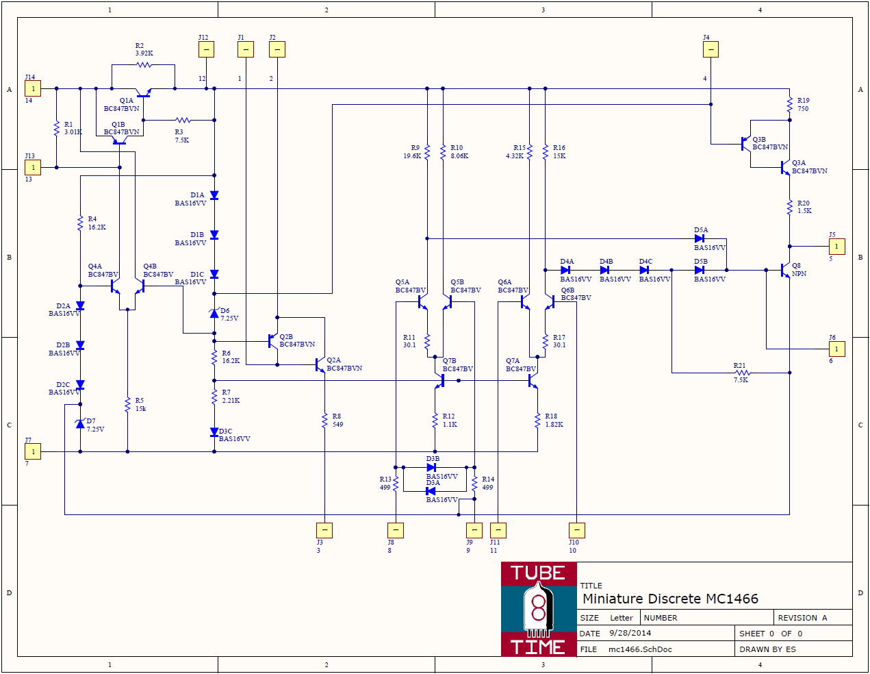
At the heart of the design is the electrostatic CRT deflection and video amplifier circuit, which takes 0-3.3V analog signals for X and Y deflection as well as the video input, and outputs high voltage drive signals to the CRT.
defl_board
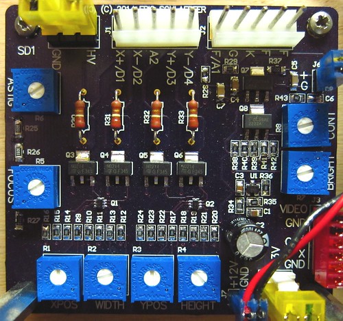
There are two deflection amplifiers, one for X and one for Y. The core of the differential amplifier is a matched dual NPN transistor with a bias circuit for setting the gain and offset (width/height and position potentiometers). A cascode stage made out of two high-voltage NPN transistors increases the bandwidth slightly and level shifts the signal up to about 1KV. There are two 220K resistors that form the load for the circuit. Don’t substitute these with plain carbon composition resistors–these parts have to be rated for high voltage use. Bandwidth of the amplifiers is about 10-15KHz, so you could drive ramp signals in to X and Y and generate an NTSC sweep if you wanted.

The video amplifier is a pretty simple class A design with a cascode stage to increase the speed. Bandwidth is about 6MHz, so the circuit can easily handle NTSC video. A simple-minded approach for driving a CRT electron gun is to ground the cathode and drive the grid negative, but the circuit design ends up being tricky. An easier way is to drive the grid to ground (or in my case, to an adjustable brightness voltage from a potentiometer) and connect the cathode to the amplifier output. The end result is the same, although there is a slight impact on the focus electrode. The video amplifier uses a +60V bias voltage which needs to be rather stiff since the drive current is fairly high (required to get 6MHz bandwidth).

A focus potentiometer produces a bias voltage for the focus grid in the CRT. It’s adjustable over a fairly wide range covering most 2″, 3″ and some 5″ CRTs, but if you’ve found some oddball CRT, you could always change some of the other resistor values.

The astigmatism potentiometer changes the final accelerator voltage relative to the average deflection plate voltages. Adjust this potentiometer if the spot on the screen looks oval instead of round.

There is a connector for a 6.3VAC filament supply. You don’t have to use an AC voltage, but be aware that pin 1 is tied to ground. You might want to measure the actual output voltage of the filament transformer (under load of course). I’ve found that most of them tend to run high (7V is not uncommon). Adding a series resistor can help prolong the life of the CRT.

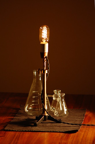
Finally, a video amplifier bias supply generates +60V for the video amplifier. As an “easter egg”, you could modify this circuit to operate as a Nixie tube power supply by changing the value of R1. You’ll also need to increase the voltage rating on C5.
bias_board
If you’ve already looked at the GitHub project, you might have noticed that there are no design files. I use Altium Designer for my schematics and PCB layouts. It’s a fantastic tool, but Altium’s decided that hobbyists are not a target market so this is a very expensive product that not many hobbyists own, so I don’t think there’s much point to posting design files. Maybe if Altium releases a noncommercial free license, but  I doubt that will happen. Altium recently raised their prices by $2K so the direction they are going in is pretty clear.

I’ll be posting updates with additional information, such as a CRT compatibility table, pin connection tables, and so forth.


CRTs with Magnetic Deflection

Projects, Uncategorized 7 Comments

Whew, Maker Faire was a lot of work, and a lot of fun!

Now that the Asteroids arcade machines are finished, I’m thinking about some suggestions that people gave me. A lot of people want a larger screen. Even with a precision 3″ CRT (3RP1A, for the curious), playing the game involves lots of squinting and hunching over.

In my collection I have a pile of 5″ CRTs, mostly electrostatic but a few magnetic. The electrostatic CRTs are quite long: 16 3/4″ is a pretty common length but some are even longer. The distance is necessary to maintain a reasonable deflection factor. 70-100 volts applied across a pair of deflection plates leads to 1″ of beam deflection. While I could certainly build a project with a very long case, this gives me a good excuse to experiment with a few of the magnetic CRTs I have.

Starting with cardboard harvested from old toilet paper rolls, I made a tube that can slip over the neck of a CRT. Next I cut 12 notches in both ends so I could hook magnet wire around them. Then I cut the whole arrangement into two halves to make it easier to wind the first set of coils on the inside of the tube.
Hand Wound Deflection Yoke
Then I wound 19 turns of wire on each half, starting with a small set of 3 turns spanning 2 notches, and then winding 7 turns across 3 notches, and finally 9 turns across 5 notches. After taping the two halves back together, I soldered the two sets of windings together in series. The polarity is critical because the magnetic fields need to add together, not cancel out. The second set of windings used the same winding pattern only this time I wound them on the outside of the cardboard tube and rotated 90 degrees.

This coil arrangement is called a semidistributed winding: look at (c) in the figure below.
Deflection Yoke Styles

After wrapping a layer of insulating tape over the windings, I wound a thin strip of soft steel around the whole thing. This provides a high permeability path for the part of the magnetic field outside of the CRT envelope. The idea behind the winding technique and all that is to create a uniform magnetic field in the path of the electron beam. The uniform magnetic field deflects the electron beam according to the Lorentz force law:
F=q(E + v x B)
E is the electric field. In this case, it’s the potential between the cathode and the anodes in the electron gun as well as the final anode. This accelerates the electrons forward towards the face of the CRT. The deflection force is the cross product of the velocity (v) and the magnetic (B) field. You can figure out the direction of force using the left hand rule. Since the electrons are moving towards the screen, a magnetic field in the up-and-down direction pushes the electron beam from side to side. This means that the horizontal deflection coils have to be positioned on the top and bottom of the CRT neck.
5AXP4 With Yoke

And it worked! I slid the yoke onto the neck of a 5AXP4 which is a CRT designed for electrostatic focus and magnetic deflection. It took nearly 1 amp to get a bit under an inch of deflection. To decrease the current I can add more windings. There’s a classic engineering tradeoff there between response speed (bandwidth) and current, since more turns have more inductance and parasitic capacitance. Incidentally, since the magnetic field strength is proportional to the current in the coils, I’ll have to drive them with a linear amplifier design that servos the current instead of the voltage.

The next step is to figure out how to handle magnetic focus. I have a 5FP14 which requires an external permanent magnet or electromagnet to focus the beam instead of the usual electrostatic lens. My friend Kent sold me a military radar display that uses a 5FP7A, and this display has a ring magnet connected with a screw and gear mechanism to adjust the focus.
5FP7A

A great resource for me has been the MIT Radiation Laboratory Series, Volume 22: Cathode Ray Displays, available here as a free PDF download. It’s full of details on how deflection and focus coils were manufactured.

I’ll leave you with this beautiful shot of the zero-first-anode-current electron gun assembly in the 5AXP4. The visible elements are (right to left): cathode, grid, accelerator, focus electrode,  and second anode (electrically tied to the accelerator).
5AXP4 Electron Gun

3D Vector Graphics

Projects 2 Comments

It’s back! This is a new vector CRT driver setup. The 3D cube is generated by an Arduino driving an 8-bit DAC.

New Table Lamp

Projects 1 Comment

Several months ago at the electronics flea market I picked up a neat bit of brass. I did some internet research and it’s actually part of a 19th century scientific demonstration instrument, most likely a prism. I found a very similar example at Fleaglass. Theirs sold for quite a bit of money, but I got mine for $5, which is probably about the value of the brass in it.

So I turned it into a table lamp.

Lamp

In the photo I’ve installed one of the many vintage-style reproduction light bulbs that are starting to appear. They don’t really look like a nice carbon filament bulb but I can use this every day and not worry about it burning out.

Now all I need to complete it is to put a shade on it. Ideas?

Lissajous Figures

Projects 6 Comments

My new CRT driver board is coming along rather nicely. Tonight I tested it out with a 5″ CRT. It uses a P7 radar phosphor so it looks bluish white with a sickly yellow persistence.

5" Cathode Ray Tube - Lissajous Figure

The pattern is a Lissajous figure (LISS-uh-joo). Take two waveform generators and connect one to the X input and the other to the Y input, and you get all sorts of interesting patterns. Since the CRT driver board is not available as a kit (not yet, anyway!) you can duplicate this with an oscilloscope and two function generators.

There’s some interesting math behind Lissajous figures, but I’m more interested in building 3KV power supplies.

« Previous Entries Next Entries »