Inside a TTL Logic IC
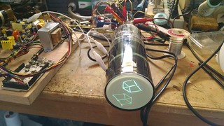
Uncategorized 2 Comments

Since 2014 is generally considered the 50th anniversary of TTL logic, I thought I’d take a TTL logic chip apart and do a little analysis.

So I started with a DM7438N, lot code M:P9006Y. Looking at National Semiconductor’s device marking convention document, I take this to mean that it was manufactured in week 6 of 1990 at a subcontractor’s fab in the United States and assembled in Malaysia.

The 7438 is a quad 2-input NAND buffer with open-collector outputs. That means the die should look symmetrical to a degree.

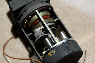
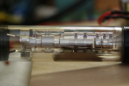
To take it apart, I used a rotary tool to carve out the encapsulation material on the top and the bottom, and then picked at it with side cutters until the chip fell out. Sadly I cracked off a corner of the die including one bond pad, but it’s still possible to figure out how it works.

What does all this do? See the image below. I’ve cropped all but one gate and highlighted the various semiconducting regions in different colors. I’ve also given designators to all the components.

Red represents the N-type collector epitaxial diffusion. Cyan represents the P-type base diffusion, and purple represents the N+ emitter region.

The schematic looks like this:

That dual-emitter transistor (Q1) sure looks strange!

How does it work? Well, if both A and B inputs are a logic high, then Q1 is off, but some current flows from R1 (4K ohm) through the base collector junction (since it is, after all, a PN junction) and feeds the base of Q2. Q2 turns on, and its emitter current feeds R3 (1K ohm) and Q3. Q3 turns on as well, and the output Y gets driven low. The non-inverted version of the output signal is available at the collector of Q3 (biased through R2, a 1.6K ohm resistor), but this particular chip doesn’t use it.

If either A or B goes low, then Q1 gets turned on. Current flows through the base emitter junction and the base gets pulled to about 0.6V above ground. No current flows through the base of Q2 because the voltage on the collector of Q1 is just too low for any current to flow. Q3 therefore stays off, and the output Y goes high impedance. By the way, this is what open collector means–the collector of the output stage transistor is left “open” with no corresponding transistor above it to pull it high.

Diodes D1 and D2 are just for input protection.

There are a couple of unused components. There is a resistor right below R1, and another resistor below R2. There are two extra transistors with a shared collector to the left of Q3. A different top metal mask could connect these extra components into the circuit and change the function of the device.

Can you think of some other gates that could be built by changing the top metal mask? Remember that there is only one metal layer which limits where you can route the traces.

XL741 – Discrete Op-Amp

Uncategorized 5 Comments

We’ve done it again! My friends at Evil Mad Scientist Laboratories have a new kit for sale. Following on the success of our Three Fives discrete 555 timer kit, we’ve had a lot of requests for a discrete 741 op-amp.

The XL741 is based on the datasheet schematic of the original uA741 op-amp IC from 1968. You can wire it up in a classic op-amp circuit and probe nodes inside the IC so you can see how the chip works. Play with differential pairs, modify the compensation, and change bias currents to your heart’s content!

Flea Market Find–Dual Gun CRT

Uncategorized 5 Comments

At the electronics flea market on Saturday, I found a 3ABP7 dual gun CRT. This one was built by DuMont, most likely intended for the 3″ version of their 5″ Type 279 Dual Beam Oscilloscope.

So of course I had to fire it up. There are two sets of deflection coils, so I drove them with one deflection board and cross-wired the deflection coils to flip the image around on the second gun.

The guns themselves have a common cathode connection and separate grids, which forces me to drive them both in parallel since my deflection board video amplifier keeps the grid at a constant potential and drives the video onto the cathode.
Dual gun 3ABP2 CRT

Here’s a closer look at the guns. The filaments are connected in parallel so this tube uses twice the normal current.
Dual gun 3ABP2 CRT

CRT Board BOM Updates

Uncategorized 1 Comment

I have corrected some mistakes in the bills of materials for the CRT driver boards (the files in GitHub have already been updated):

  • ScopePower U2 part number from TS271CN (DIP package) to TS271IDT (SOIC).
  • ScopePower R3 part number from VR37000003305JR500 (33 meg) to VR37000001005JR500 (10 meg).

If you already ordered parts, I apologize. The TS271CN is a great little op amp and the DIP package version will work fine in a breadboard. That’s what I will do with the ones I accidentally ordered. The 33 meg resistor is useful as a bleeder resistor if you build the post deflection acceleration module (to be posted soon).

P10 Dark Trace CRT – The Skiatron

Uncategorized 3 Comments

I have a little story to tell. Years ago, I met someone who had a very large collection of CRTs. He had everything from common 3BP1s all the way to rare little gems like the 1EP1 and some vintage prototype CRTs. He showed me an item in his collection which was a rectangular CRT with a P10 phosphor. Finding a CRT with the P10 phosphor is like finding a unicorn. P10 is not really a phosphor; it designates a screen coated with some sort of alkali-halide (potassium chloride) that darkens when hit with an electron beam–a scotophor. The darkening effect lasts until the coating is heated, and typical P10 CRTs have a built-in heater that erases whatever was recorded on the screen.

Anyway, a few years go by and I lose contact with the guy. Rumors are flying around, and it turns out that he has decided to sell his entire collection. Bits and pieces of it start showing up at auction houses and flea markets. Another friend of mine mentions that he picked up a lot of CRTs at an auction house and asked if I wanted to pick through it. While sorting through it, I recognized the rare beast and bought it on the spot.

P10 Dark Phosphor CRT

So I finally got the time to hook it up and try it out. There doesn’t seem to be any documentation. The part number is 06E024P10, made by Thomas Electronics. It works, but not particularly well. Since the pin connections are nonstandard and the electron gun has some extra elements, I’ve probably got it connected all wrong. Anyway, I was able to put some scribbles on the screen.

P10 Dark Phosphor Screen

Notice the dark purple areas. I am shining a lamp through an aperture in the top of the CRT.

P10 Dark Phosphor Screen

Looking through the aperture, you can see how the CRT has a standard green phosphor section on the top third. This might have been used to verify that the tube’s electron gun was in focus. It could also have been used for status information. Most likely this tube would have been used in an early form of storage oscilloscope for capturing single-shot high speed events, although most examples of P10 tubes were designed for radar displays.

CRTs with Magnetic Deflection

Projects, Uncategorized 7 Comments

Whew, Maker Faire was a lot of work, and a lot of fun!

Now that the Asteroids arcade machines are finished, I’m thinking about some suggestions that people gave me. A lot of people want a larger screen. Even with a precision 3″ CRT (3RP1A, for the curious), playing the game involves lots of squinting and hunching over.

In my collection I have a pile of 5″ CRTs, mostly electrostatic but a few magnetic. The electrostatic CRTs are quite long: 16 3/4″ is a pretty common length but some are even longer. The distance is necessary to maintain a reasonable deflection factor. 70-100 volts applied across a pair of deflection plates leads to 1″ of beam deflection. While I could certainly build a project with a very long case, this gives me a good excuse to experiment with a few of the magnetic CRTs I have.

Starting with cardboard harvested from old toilet paper rolls, I made a tube that can slip over the neck of a CRT. Next I cut 12 notches in both ends so I could hook magnet wire around them. Then I cut the whole arrangement into two halves to make it easier to wind the first set of coils on the inside of the tube.
Hand Wound Deflection Yoke
Then I wound 19 turns of wire on each half, starting with a small set of 3 turns spanning 2 notches, and then winding 7 turns across 3 notches, and finally 9 turns across 5 notches. After taping the two halves back together, I soldered the two sets of windings together in series. The polarity is critical because the magnetic fields need to add together, not cancel out. The second set of windings used the same winding pattern only this time I wound them on the outside of the cardboard tube and rotated 90 degrees.

This coil arrangement is called a semidistributed winding: look at (c) in the figure below.
Deflection Yoke Styles

After wrapping a layer of insulating tape over the windings, I wound a thin strip of soft steel around the whole thing. This provides a high permeability path for the part of the magnetic field outside of the CRT envelope. The idea behind the winding technique and all that is to create a uniform magnetic field in the path of the electron beam. The uniform magnetic field deflects the electron beam according to the Lorentz force law:
F=q(E + v x B)
E is the electric field. In this case, it’s the potential between the cathode and the anodes in the electron gun as well as the final anode. This accelerates the electrons forward towards the face of the CRT. The deflection force is the cross product of the velocity (v) and the magnetic (B) field. You can figure out the direction of force using the left hand rule. Since the electrons are moving towards the screen, a magnetic field in the up-and-down direction pushes the electron beam from side to side. This means that the horizontal deflection coils have to be positioned on the top and bottom of the CRT neck.
5AXP4 With Yoke

And it worked! I slid the yoke onto the neck of a 5AXP4 which is a CRT designed for electrostatic focus and magnetic deflection. It took nearly 1 amp to get a bit under an inch of deflection. To decrease the current I can add more windings. There’s a classic engineering tradeoff there between response speed (bandwidth) and current, since more turns have more inductance and parasitic capacitance. Incidentally, since the magnetic field strength is proportional to the current in the coils, I’ll have to drive them with a linear amplifier design that servos the current instead of the voltage.

The next step is to figure out how to handle magnetic focus. I have a 5FP14 which requires an external permanent magnet or electromagnet to focus the beam instead of the usual electrostatic lens. My friend Kent sold me a military radar display that uses a 5FP7A, and this display has a ring magnet connected with a screw and gear mechanism to adjust the focus.
5FP7A

A great resource for me has been the MIT Radiation Laboratory Series, Volume 22: Cathode Ray Displays, available here as a free PDF download. It’s full of details on how deflection and focus coils were manufactured.

I’ll leave you with this beautiful shot of the zero-first-anode-current electron gun assembly in the 5AXP4. The visible elements are (right to left): cathode, grid, accelerator, focus electrode,  and second anode (electrically tied to the accelerator).
5AXP4 Electron Gun

Asteroids Mini Arcade Machine

Uncategorized 14 Comments

Here’s a tiny Asteroids arcade machine I built from scratch. It uses a vintage 3″ round cathode ray tube driven from an amplifier board and high voltage supply of my own design.

A friend of mine ported his 6502 emulator to an STM32F4 Discovery board so this arcade machine is able to run the original Asteroids program without any modifications. The STM32F407 processor has two DAC outputs which work perfectly for driving the X and Y deflection inputs on the amplifier board.

Turns out the ST Micro part is really good for driving displays like this. Not only do the DAC outputs work great for deflection, but the hardware floating point really speeds up things like 3D vector rotation.

Come find me at the Bay Area Maker Faire! (May 17 and 18–go buy your tickets now!) I will be located in the Fiesta Hall (the dark room with the Tesla coils). I’ll set up a second arcade machine running some additional demos, including a Super Secret Game. You’ll just have to come and find out what it is.

Three Fives – Discrete 555 Timer

Uncategorized No Comments

My friends at Evil Mad Scientist have a new kit for sale. It’s a 555 timer circuit that you can build yourself using discrete transistors. You can wire it into all sorts of 555 timer circuits and then probe individual nodes to see how the chip actually works.The circuit board that you get with the kit has silkscreen labels that mark the functional blocks of the circuit, and silkscreened component designators that match up with the “official” Signetics schematic.

The circuit is full of interesting analog electronic design elements. You’ll be able to play with differential pairs, current mirrors, Darlington stages, diode-connected transistors, and more.

It’s a great kit if you want to learn more about how integrated circuits work, or if you’re a fan of the indefatigable 555 timer and want to have a neat conversation piece, or even if you’re just a beginning electronics hobbyist and you want to practice your electronics assembly and soldering skills.


CRT Driver Kit Update

Uncategorized 8 Comments

It’s been quite some time since I last posted about this. The project has been on the back burner for some time now since I’ve just been so busy with other things. It’s actually pretty far along the process but the cost of the parts is just too high, and the kit has quite a few parts.

I’ve been revisiting the design again to see if I can make it easier to build and less costly.

A question: Would you consider a version without a DAC? Instead of having an 8-bit digital interface (Arduino compatible), it would have analog X and Y inputs and a video/blanking input.

Quick Note

Uncategorized No Comments

If the site’s been very slow for you lately, it’s because someone used a PHP injection attack to add some potentially malicious Javascript to the top of the page. It should be fixed now. Thanks to Olli for the tip.

« Previous Entries Next Entries »