IEE Clock

Clocks, Projects 7 Comments

Update: more photos and information in the followup post.

Wow, things have been very busy lately–I moved to a new apartment, traveled to China, attended my brother’s wedding, and still had time to finish another clock!

IEE Clock - Front View

This one actually does have filaments. There are 12 light bulbs per digit; one for each numeral, and two for decimal points (left and right). These are neat little display modules that were made by a company called IEE (Industrial Electronic Engineers) way back before 7-segment LEDs were invented. Each light bulb sits behind a clear printed slide with the corresponding number printed on it in negative (the number is clear and the background is black), and in front of the slide is an array of tiny lenses. When a light bulb turns on, it projects an image of the number through the lens and onto the back of the lightly frosted plastic at the front of the display module. The Vintage Technology Association has a great exploded view so you can get a better idea of how this works.

IEE Clock - Front Panel

The clock itself is fairly pedestrian although this design uses a quadrature encoder (the black knob on the upper right) to set the time. Instead of pushing on a button and waiting while the numbers slowly tick by, it’s much easier to just spin a knob.

Keeping time is the function of a DS3231 IC. The display is not multiplexed. A multiplexed display would involve a lot of diodes which would dissipate quite a bit of heat, and for this design, I use 6 ULN2003 driver ICs connected to 2 MAX7300 GPIO expanders. Technically I used devices that are pin compatible with the ULN2003 since nobody seemed to have any in stock. The microprocessor is a PIC18F2420 which communicates with the DS3231 and both MAX7300 devices using I2C.

Here is the back of the clock. You can clearly see the vents which allow the heat from the light bulbs to dissipate.

IEE Clock - Rear Panel

This clock will be at Maker Faire, so if you plan to attend, feel free to stop by my booth and take a look in person.

1948 Philco 48-225 Table Radio

Restoration 3 Comments

Recently I completed restoring a Philco 48-225 AM tube radio. This radio was produced by Philco in 1948, and it was one of the first radio models to have a plastic (polystyrene) case instead of a bakelite case.

When I received the radio, the case was pretty scratched and banged up, and there was a big crack on the left side. Inside was a lot of dust and bits of dried leaves. Most of the tubes were missing, and the ones that came with it were the wrong type.

The case cleaned up nicely after a lot of wet sanding with fine-grit sandpaper and polishing with Novus 1, 2, and 3. The gold paint on the speaker grill was flaking off, but I decided to leave it alone. I saw a photo of the same model radio on eBay and someone had ruined the grill by trying to polish it–the gold paint is a very thin layer and it came off in patches.

Using superglue I fixed the crack and sanded it so that it’s barely visible. I hear you can also use a solvent-type glue, but I didn’t have any. The superglue repair is probably fragile so I will have to be gentle.

Philco 48-225 - Standing Proud
Turning the radio around, you can see the “All-American Five” tube complement. They are the 7A8 converter, the 14A7 IF amplifier, the 14B6 2nd detector/1st audio AVC, the 50L6GT audio output amplifier, and the 35Z5GT rectifier. All the tubes except for the 35Z5GT are of the Loctal variety. Unfortunately the back cover of the radio is missing.
Philco 48-225 - Glows Inside
Here is the underside of the chassis before I restored it. You can see how the paper capacitors are coming apart due to age. These radios were designed to be very low cost and were not supposed to last a very long time. The sectional electrolytic capacitor (the long pale tube on the upper right) in particular did not work at all because the electrolyte had seeped out completely.
Philco 48-225 - Innards
I ended up replacing most of the capacitors. For this restoration I pushed the guts out of each capacitor and slipped the new capacitor inside the old one, sealing the ends with wax. This keeps the underside looking authentic.

Notice that there is no power transformer inside this radio. This radio operates directly off the AC line. The filaments for all 5 tubes are wired in series and the voltage ratings add up to the line voltage. The chassis itself is not grounded and it is actually part of the antenna circuit. There is a 150K resistor connecting it to one side of the AC line. The plug is not polarized so it’s quite easy to shock yourself on any exposed metal. It’s not a good idea to plug it straight into a wall socket because of this. If you try to add a 3 conductor line cord with the ground prong connected to the chassis, this will short out the radio’s antenna and the radio won’t work.

The solution is to use an isolation transformer. I have one connected to a Variac that I use to adjust the line voltage. When I first powered up the radio, I ramped the voltage up slowly to make sure there were no problems along the way. I also measured the line voltage and set it to 115V instead of 120V. AC line voltage was a little lower back in 1948. The difference doesn’t sound like much but running at the higher voltage would apply 6.6V to a tube filament rated at 6.3V. This is enough to reduce the life of the tube.
Variac and Isolation Transformer
With the radio plugged in to the isolation transformer, the radio “floats” relative to the AC line, and it’s safer to touch exposed metal. It’s still a high voltage circuit so the one-hand rule applies. When the radio is isolated like this, it’s also safe to connect it to pieces of test equipment, such as an oscilloscope. The oscilloscope probe ground actually connects to the ground pin on the oscilloscope’s line cord, so if I had tried to test the radio when it was plugged straight in, I could have caused a short circuit that would have melted my scope probe.

It sounds pretty good now and it adds a vintage touch to the living room decor.

Philco 48-225 - Fully Restored

Yes, Still Alive

Projects No Comments

OK, it’s been a while since I’ve posted–a long summer involving friends, BBQs, weddings, hiking, and other social activities. Now that the “cold dark California winter” is setting in, I’m spending more time on projects. Here’s a peek at the latest one.

My messy workbench:
What's This? - Part 2

What’s this? It looks like the beginning of a wiring harness.
What's This? - Part 1

Can anyone guess what this is?

2-Axis Joystick From VCR Parts

Projects 7 Comments

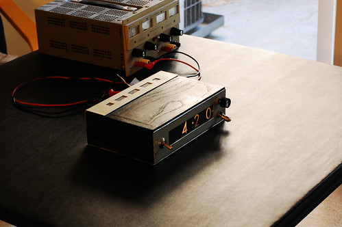
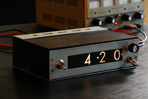
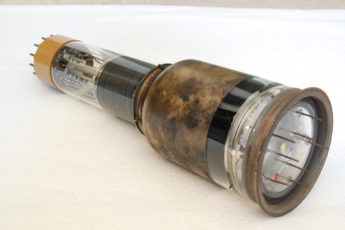
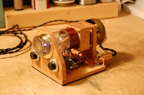
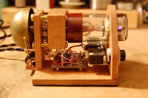
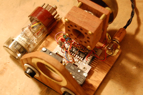
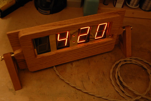
One of my CRT clocks has a small joystick on the front which is used to set the time. I built it a while ago using an idler wheel from an old VCR.

Second Scope Clock - Front Panel

Well, the other day I found another idler wheel from the same VCR, and I decided to share the construction technique so that you can make one too. It’s pretty simple and takes an hour or two. You will need a VCR idler wheel that looks like the one in the picture below, four microswitches (you can scavenge these from an old computer mouse), a spring, and a piece of sheet steel to mount the whole arrangement on. The sheet metal must be steel for reasons I will discuss later.

Joystick - Parts

First, take apart the idler wheel by gripping the top washer with a pair of vise-grips, taking care not too dent it too much. Grab the metal shaft with another pair of pliers and pull the assembly apart. Slide off the screw thread and the metal washer, and take the top washer (which has a convex side and a flat side), and slide it back on to the metal shaft about halfway.

Joystick - Parts Ready to Go

Drill a hole in the sheet metal, and make the hole somewhat larger than the shaft. For my joystick I used a 3/32″ diameter drill. Insert the metal shaft into the hole so that the convex part of the washer faces down against the sheet metal. Turn the piece of sheet metal over and drop a spring over the shaft, then press the remaining metal washer onto the shaft so it captures the spring and tensions it slightly. If you’ve done things correctly, when you push the shaft to the side, it will spring back to the middle. You may need to adjust the spring tension if the shaft doesn’t return all the way. If the shaft can’t move very much in any direction, you’ll need to enlarge the hole.

Joystick - Spring Return Mechanism

In the previous picture, you can see how the convex side of the washer allows the joystick to “roll” against the surface of the sheet metal. When you let go of the shaft, the spring tension pushes the shaft back to the center. The joystick action puts a lot of wear on the sheet metal which is why it’s important to use steel instead of a softer metal like brass or aluminum.

Now it’s time to begin mounting the switches to the sheet metal. You may want to lay them out by hand first just to make sure there is room for them all, and that the actuators end up in the right position. Skip ahead a few photos to see how I arranged my switches.

Joystick - Switch Positioning

Position the switch so that the washer on the reverse side of the sheet metal will hit the actuator just right. You don’t want the washer pushing in too hard–the hole in the sheet metal should stop the shaft from moving to the side rather than the actuator in the switch itself. At this point you may need to adjust the bottom washer so that it lines up with the switch actuator. In my joystick, I had to use a different spring to get the correct tension when the bottom washer was lined up correctly.

When you are finished lining it up, mark the sheet metal where the hole should go (I just dropped a drill bit in the switch’s mounting hole and twirled it between my thumb and forefinger, holding the switch down with my other hand). After you drill the first hole, put a small machine screw into the hole and secure it with a nut on the other side. You can rotate the switch to fine tune its position so the washer hits it in the right place. When it’s dialed in, mark and drill the next hole.

Joystick - One Switch Mounted

In this photo most of the switches are mounted, and you can see that I’ve drilled one mounting hole for the last switch.

Joystick - 3/4 Done

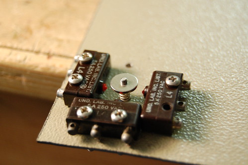
Once the last switch is mounted, take a look at the following photo and make sure that your washer hits every switch actuator correctly.

Joystick - Pushing One Button

At this point I drilled some mounting holes in the corners and took the whole thing apart, and cut the mounting plate out of the larger piece of sheet steel. It’s easier to work with a larger piece of sheet metal when drilling holes and such rather than a tiny piece that is harder to clamp. After putting everything back together, the joystick now looks like this:

Joystick - Completed

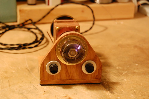
The joystick is finished, and it’s ready to be mounted in a front panel. For this joystick, I’ll probably mount it behind a 1/4″ thick piece of oak, so I will drill a big round hole for the joystick shaft and then use wood screws to mount the metal plate to the back of the wood. To dress up the front, I could use a piece of brass pierced with a plus-sign-shaped cutout to cover the hole in the wood like I did on my CRT clock in the first picture. As a finishing touch, I will mount a small wooden knob or perhaps a brass bead on the end of the joystick shaft.

Neon Lamp Leakage Current

Projects No Comments

For another project in progress, I needed to test the “off” leakage current of neon bulbs. Along the way I discovered some interesting things. First, let’s take a look at the test subjects.

Neon Lamps Used for Leakage Tests

The lamp on the left side is a brand new miniature-type, the middle lamp pretty much represents the average neon lamp, and the lamp on the right is a special “frosted” lamp that I pulled out of some old equipment. Sorry, I do not have type numbers for these lamps, and they are not marked. Some older neon lamps were marked with the type number when the seal was crimped.

The testing used a power supply adjustable from 0V to 40V and a Fluke 87 multimeter. Any good multimeter with a 10MΩ input impedance can be used to measure extremely low currents by wiring the meter in series (like an ammeter) while it is in volts mode. Tests of the tiny neon lamp and the “average” neon lamp used the meter in mV mode, while tests of the frosted lamp used the volts mode. The tests were conducted at room temperature at normal indoor lighting conditions. Before testing, each lamp was washed with 90% isopropyl alcohol and dried with canned air.

Neon Lamp Leakage Current

There are some very interesting observations to be made with this data. The tiny lamp exhibits very low leakage current, peaking at 200pA. The “average” neon lamp peaks at 2nA, and the frosted lamp peaks at 263nA. I tried a few more lamps of each type and although they vary quite a bit, each type of lamp approximates the same current as the data above. It is due to the construction of the lamps themselves. According to Techlib.com, the increased leakage current is due to the radioactive thorium present in the lamp electrodes.

If it’s possible for radiation to increase the leakage current, I surmised that a strong light source could increase it as well. Taking another “average” neon lamp, I measured a leakage of 2.8nA at 40V. When exposed to a very bright white LED flashlight, the leakage current increased to 11.0nA, and when exposed to an ultraviolet LED flashlight, the leakage current climbed to 16.6nA. It may be that the photons impinging on the electrodes cause electrons to “leap” from the outer electron shell of the metal atoms and drift (due to the electric field between the two electrodes) across to the opposing electrode. This shows up as the increased drift current.

By increasing the temperature of a neon bulb, I was able to increase the leakage current as well. At the same time, I discovered that some small amount of water vapor still remained as a film on the surface of the bulb. For the case of the tiny neon bulb, the leakage current of 200pA fell to 50pA after a few seconds of applied heat, invalidating my previous experiments. As the temperature of the bulb increased, the leakage current increased to 1100pA before I removed the heat. This principle is the same one that enables vacuum tubes to operate–the heated cathode generates a space charge “cloud” of electrons that drift depending on the applied potential.

For my application, I would rather not have any thorium in the lamp since I want the leakage current to be as low as possible.

Nixie Tubes!

Cleverness 1 Comment

Recently I purchased a number of nixie tubes from the local electronics flea market:

Nixie Tubes

A few of them caught my eye. This Burroughs B-5448 one was most likely used in a calculator or possibly a meter to indicate plus and minus as well as the overload condition.

Burroughs B-5448 Nixie

And this National NL-989 was used for indicating the unit or mode of a multimeter. There are two “partitions” in this nixie tube: one contains the symbols “A”, “M”, and “K”, while the other contains “C”, “V”, and “Ω”. The multimeter would have used this to indicate “AC”, “MV”, “KV”, “MΩ”, “KΩ”, and so on.

National NL-989 Nixie

Notice how the glow is a different color in each tube? My camera did an excellent job of reproducing the correct color, so what you see is very close to what the ionized gas actually looks like. The National tube appears to contain mostly neon, while the Burroughs shows light blue “fringing”, indicating the presence of mercury, which was used to increase the lifespan of the tube.

RCA 6499 Radechon

Cleverness No Comments

At the electronics flea market I found a rather interesting-looking vacuum tube. It appears to be a CRT but with a metal cap at the end.
Radechon

As it turns out, this device is a memory which could have been used in some old computers, storing around 16 kilobits. It could also have been used in radar systems for converting polar coordinate-based sweeps to raster sweeps (like a TV). The socket end contains an ordinary electron gun like the one found in a CRT, but the front end does not contain the usual phosphor screen. Instead, there is a 1mil thick sheet of mica with a fine grid of wires laid on top. On the other side of the mica there is a metal plate.
Radechon
Here’s a closeup showing the metallic screen on the front. The mica underneath capacitively stores electrons that are laid down by the electron beam. This memory can store analog waveforms since higher voltages are represented by a higher density of electrons at a particular spot, and lower voltages correspond with a lower electron density.
Radechon

Data for the tube is available from David Forbes.

Here are a couple of other sites with information:

Åke’s Tubedata

World Power Systems

Virtual Valve Museum

Cold War Infrastructure (A full-page RCA ad for the device)

Dekatron Kitchen Timer

Projects 10 Comments

Recently I completed the construction of a Dekatron-based kitchen timer. A Dekatron is an electronic counting device used in the middle of the 20th century for counting pulses or dividing input pulses. You can find a very good introduction to the devices at Mike’s Electric Stuff. My timer is certainly not the first. This gentleman has created a rather military-looking kitchen timer that uses three Dekatrons.

Dekatrons are relatively difficult to find, so I decided to use a single Dekatron in my timer. Actually this project is an old one that I revisited. The original project was just going to be a spinner, but I had trouble with the driving circuit (it never worked reliably). For the 2008 Maker Fair I dusted it off and tried to power it up–with 12V instead of 5V. The power supply and microcontroller did not appreciate it and the whole thing stopped working. The second time around I decided to turn it into something useful. Here it is.

Dekatron Kitchen Timer - Corner View

The driving circuit in the Dekatron kitchen timer is based on a circuit drawn up by Mike Moorrees. You can find the circuit at the NEONIXIE-L mailing list files section. There’s a good excuse for you to join. If you’re interested at all in antique display devices (not just Nixie tubes) you need to join.

Dekatron Kitchen Timer - 20 Minutes

There are twenty minutes remaining on the timer. You can read the time using the scribed lines on the brass ring around the Dekatron. The ionized gas in the tube glows purple because of the high argon content.

Dekatron Kitchen Timer - Side View

In this side view, you can clearly see the high voltage power supply. It has a copper-wound ferrite toroid. The power supply converts 5V up to 450V by a MAX845 that pulses the transformer at 535KHz, and the 150V output of the transformer gets stepped up to 450V through a 3-stage voltage multiplier.

Time is kept and the clock is controlled by a PIC16F84. The brass bell at the end rings once the timer expires. After ringing the bell, the PIC turns off the high voltage supply and enters sleep mode. Pressing a button wakes up the microcontroller and begins a timing cycle.

Dekatron Kitchen Timer - Socket

You can see the socket more clearly when the Dekatron is removed. My homebrew drill press for my Dremel tool helped tremendously to drill accurately-placed holes for the pins.

On the right side the power connector provides 5V to the timer from an old cellphone charge adapter. Don’t throw away these adapters! The small ones often contain a very simple off-line isolated power supply that can be modified to produce other output voltages. You can recycle them for projects quite easily. Perhaps I will write an article on this.

The 5-pin connector on the board is used to program the PIC. The PIC16F84 is old enough that it does not support in-circuit debugging. It was Microchip’s very first product on their flash process which has made them so much money over the intervening years.

Dekatron Kitchen Timer - Dekatrons!

Here is the extent of my Dekatron collection. They are all type GS10D, which is a decimal selector tube with two sets of guide electrodes. The Dekatron in the front of the timer does not work. Can you see why?

Steampunk Timekeeping Instrument

Projects No Comments

Here’s a recent product of my workshop. A week of sawing wood, drilling, carving with my Dremel, slicing brass with tin snips, polishing, sanding, and staining resulted in this brand new limited edition (of one) Steampunk timekeeping instrument.
Steampunk Timekeeping Instrument
This device is based on the Panaplex clock circuit I built a while back. The displays are seven segment but, like Nixie tubes, are filled with Neon gas. To match them, the colon and PM indicator use small neon lamps.

Construction is stained oak with brass fittings. The device is exactly one inch thick. It can pivot about the two knurled brass nuts on either end.
Steampunk Timekeeping Instrument

But how does power enter this timekeeping device? It travels through brass terminals (with appropriately colored washers to indicate the polarity) up to the pivot, where it enters the case of the timepiece. Look on the inside edges of the wooden stands, and you will see the polished brass strips that carry the direct current up to the knurled nuts from the terminals.
Steampunk Timekeeping Instrument  - Upside Down

Now for the technical details. The timepiece uses a PIC18F242 running at 4MHz. The time is kept by an exceptionally tiny sliver of quartz imbedded within a miniature silver cylinder–a 32KHz watch crystal. My standard 180V power supply provides the high voltage needed by the Panaplex display elements. Here is the timekeeping instrument with the two halves of the case separated.
Steampunk Timekeeping Instrument - Laid Out

My other designs are usually drawn out in AutoCAD, but this time I decided to use the old fashioned method. The two triangular wooden stands on the end took some tricky geometry. The pivot is exactly 3″ up from the lower edge of the base. The angle of the triangle is 70 degrees, because 60 didn’t look right and 80-90 was too peaky looking.

The switches I found at HSC Electronic’s yearly sale. I like to use unusual looking switches and controls in my projects. I feel very sad when I see someone’s awesome project that has been defiled by cheap-looking Radio Shack switches.

The Steampunk timekeeping device was made using a simple setup of a junior hacksaw (6″ long), an old cordless drill, a Dremel, a Dremel drill press, and numerous small hand tools. Most of the work happened on the back patio of my apartment. Yes, it’s possible to be a Maker even in the big city.

Coby DP-151SX Hacking – LCD Extraction and Interrogation

Cleverness, Projects 21 Comments

In this previous post I disassembled the Coby DP-151SX digital picture frame. This device is very hackable, and includes a lot of goodies such as a Li-Ion battery and battery charger circuit as well as a neat little color LCD display with a white LED backlight. The pinout for the LCD is in the previous post.

The MAXQ2000 microcontroller development board I have uses a 0.1″ spacing header to connect to the I/O pins, so I made a little adapter and wired it up to the LCD connector using wire-wrap wire. It uses 13 I/O lines, but that could be reduced 11 if CS# is wired to ground and RST# tied to a separate reset IC (such as a MAX811). It’s actually a good idea to use CS#, because you can then multiplex the functionality of all the other pins and recover that I/O.

Here is a picture showing the LCD up and running with a simple test pattern:
Coby DP-151 Photo Keychain - LCD Extraction and Interrogation

It’s not 128×128, but actually 132×132 pixels. The color depth is 16-bit using a fairly standard 5-6-5 bit encoding. See the PCF8833 datasheet for more details.

Spark Fun has a similar LCD display which uses the same controller, only it costs $20. Amazon.com sells the Coby-151SX in black for $10. Not a bad deal: for $10 less you get a Li-Ion battery, mini-USB cable, and a driver CD, which you could use as a coaster for your Mountain Dew to help with the LCD programming. Spark Fun has some sample code which you should easily be able to adapt for parallel mode (since the Coby LCD connector brings out the parallel data lines, unlike the Spark Fun LCD).

The source code for my test program will get posted once I clean it up and possibly add functionality (Character fonts? Bit blitters?)

« Previous Entries Next Entries »