Neon Lamp Leakage Current
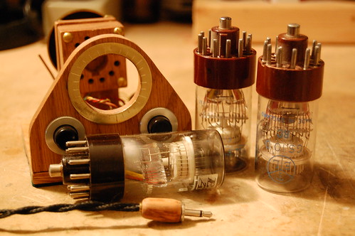
April 13, 2009 Projects No CommentsFor another project in progress, I needed to test the “off” leakage current of neon bulbs. Along the way I discovered some interesting things. First, let’s take a look at the test subjects.
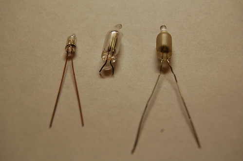
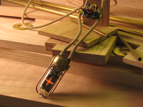
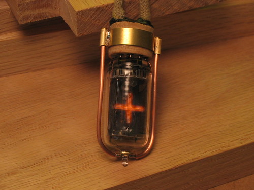
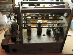
The lamp on the left side is a brand new miniature-type, the middle lamp pretty much represents the average neon lamp, and the lamp on the right is a special “frosted” lamp that I pulled out of some old equipment. Sorry, I do not have type numbers for these lamps, and they are not marked. Some older neon lamps were marked with the type number when the seal was crimped.
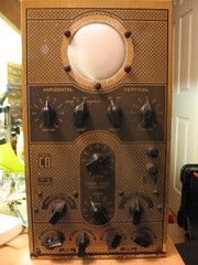
The testing used a power supply adjustable from 0V to 40V and a Fluke 87 multimeter. Any good multimeter with a 10MΩ input impedance can be used to measure extremely low currents by wiring the meter in series (like an ammeter) while it is in volts mode. Tests of the tiny neon lamp and the “average” neon lamp used the meter in mV mode, while tests of the frosted lamp used the volts mode. The tests were conducted at room temperature at normal indoor lighting conditions. Before testing, each lamp was washed with 90% isopropyl alcohol and dried with canned air.
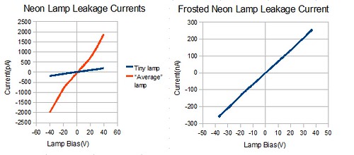
There are some very interesting observations to be made with this data. The tiny lamp exhibits very low leakage current, peaking at 200pA. The “average” neon lamp peaks at 2nA, and the frosted lamp peaks at 263nA. I tried a few more lamps of each type and although they vary quite a bit, each type of lamp approximates the same current as the data above. It is due to the construction of the lamps themselves. According to Techlib.com, the increased leakage current is due to the radioactive thorium present in the lamp electrodes.
If it’s possible for radiation to increase the leakage current, I surmised that a strong light source could increase it as well. Taking another “average” neon lamp, I measured a leakage of 2.8nA at 40V. When exposed to a very bright white LED flashlight, the leakage current increased to 11.0nA, and when exposed to an ultraviolet LED flashlight, the leakage current climbed to 16.6nA. It may be that the photons impinging on the electrodes cause electrons to “leap” from the outer electron shell of the metal atoms and drift (due to the electric field between the two electrodes) across to the opposing electrode. This shows up as the increased drift current.
By increasing the temperature of a neon bulb, I was able to increase the leakage current as well. At the same time, I discovered that some small amount of water vapor still remained as a film on the surface of the bulb. For the case of the tiny neon bulb, the leakage current of 200pA fell to 50pA after a few seconds of applied heat, invalidating my previous experiments. As the temperature of the bulb increased, the leakage current increased to 1100pA before I removed the heat. This principle is the same one that enables vacuum tubes to operate–the heated cathode generates a space charge “cloud” of electrons that drift depending on the applied potential.
For my application, I would rather not have any thorium in the lamp since I want the leakage current to be as low as possible.